6
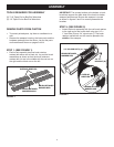
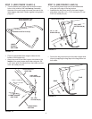
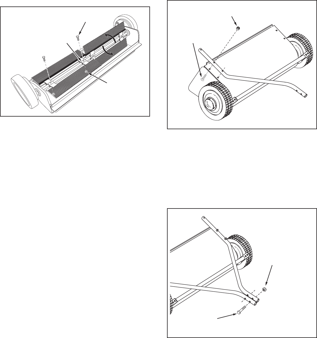
FIGURE 4
STEP 4: (SEE FIGURE 4)
• Cutofftheplastictiethatholdstheheightadjustment
tubeinplace.
• AssembletheR.H.hitchtubetothesweeperhousing
usingtwo5/16"x1-1/2"carriagebolts(C),andtwo
5/16"nylocknuts(J).Do not tighten yet. Repeat for
theL.H.hitchtube.
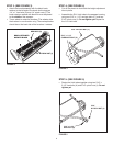
FIGURE 3
STEP 3: (SEE FIGURE 3)
• Attachthebrushassemblywiththeblackbrush
retainertotheleftendofthebrushshaftusingtwo
1/4"x1"hexbolts(G)and1/4"nylocknuts(I).The
brushretainermarkedwithblackinkmustbeplaced
to the middle of the sweeper.
• Turnawheeltorotatethebrushes.(Thewheelsdrive
thebrushesinonedirectiononly.)Theoverlapbristles
shouldbeonthebacksideofthebrushasitrotates.
1/4" x 1"
HEX BOLT (G)
1/4" NYLOCK NUT (I)
BRUSH RETAINER
MARKED BLACK
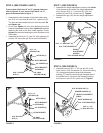
5/16" x 1-1/2"
CARRIAGE BOLT (C)
5/16" NYLOCK NUT (J)
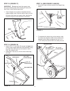
STEP 5: (SEE FIGURE 5)
• Fastenthehitchtubestogetherusingtwo5/16"x
2-1/2"hexbolts(A)and5/16"nylocknuts(J).Do not
tighten yet.
5/16" x 2-1/2"
HEX BOLT (A)
5/16"
NYLOCK NUT (J)
FIGURE 5


