2. Set the parking brake and push the vehicle. Ifthe
rear wheels roll,adjust the brake following
instructionson page 20.
Tires
_lb ARNING: Never exceed maximum limitofair pressure shown on sidewall of the tire.
The recommended operating tire pressure is 20-22 psi
for both sets of tires. Refer to the tire sidewall for exact
tire manufacturer's recommendation. Do not
ovednflate. Uneven tire pressure could cause the
cutting deck to mow unevenly.
Battery
The battery is located under the cup holder to the right
ofthe seat. The positive battery terminal is marked Pos.
(+). The negative battery terminal ismarked Neg. (-).
_ ARNING: Battery posts, terminals and
related accessories contain leadand lead
compounds. Wash hands after handling.
• Always keep battery cables and terminals clean
and free of corrosive build-up.
• After cleaning, apply a lightcoat ofpetroleum jelly
or grease to bothterminals.
• Always keep the rubber boot positioned over the
positive terminal to prevent shorting.
• Ifremoving the battery for any reason, disconnect
the NEGATIVE (black) wirefrom itsterminal first,
followed by the POSITIVE (red) wire. When re-
installingbattery, always connect the POSITIVE
(red) wire to itsterminal first, followed by the
NEGATIVE (black) wire.
IMPORTANT:Be certain that wires are connected to the
correct terminals; reversing them couldchange poladty
and cause damage to the engine's alternating system.
• Check fluid level inside each cell of the battery
every two weeks and before and after charging.
Always maintain level just below the split rings.
• Add onlydistilled water. Never add additional acid
or any other chemicals tothe battery after initial
activation.
NOTE: ff you have operated the tractor for a long
period, check the fluid level of the battery as it can
overheat and lose fluid.
Connecting Battery Cables
To reconnect battery cables, ifthe battery was removed
for some reason, follow instructionsbelow.
1.
2.
Remove throe screws holdingthe cup and battery
holderto the frame ofthe unit.
Remove red and black insulationcaps from battery
terminals.
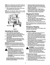
_r !' //
l 1 \ Cable j
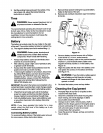
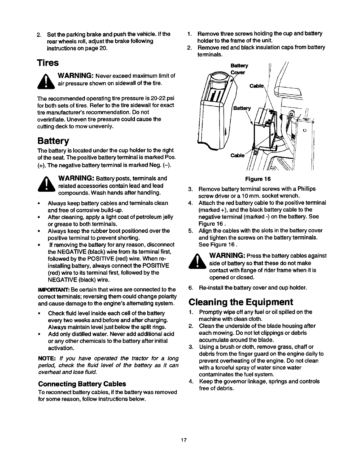
Figure 16
3. Remove batteryterminal screws with a Phillips
screw driver or a 10 mm. socket wrench.
4. Attach the red battery cable tothe positiveterminal
(marked +), and the black battery cable tothe
negative terminal (marked -) on the battery. See
Figure 16.
5. Align the cables with the slots inthe battery cover
and tighten the screws on the batteryterminals.
See Figure 16.
WARNING: Press the battery cables against
side of battery sothat these do not make
contact with flange of riderframe when itis
opened or closed.
6. Re-install the battery cover and cup holder.
Cleaning the Equipment
1. Promptly wipe off any fuel or oilspilled on the
machine with clean cloth.
2. Clean the underside of the blade housing after
each mowing. Do not letclippings or debits
accumulate around the blade.
3. Using a brush or cloth, remove grass, chaff or
debds from the finger guard on the engine daily to
prevent overheating ofthe engine. Do not clean
with a fomeful sprayof water sincewater
contaminates the fuel system.
4. Keep the governor linkage, springsand controls
free of debris.
17


