


21
SERVICE AND MAINTENANCE
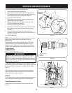
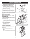
threadsoftheinputshaft.Torquethehexscrewto250-325in.
/lbs.tosecuretheaugerpulleyassemblyontheinputshaft.
12.Ifalsoreplacingthedrivebelt,proceedtothe“DriveBelt”
instruction.Ifnot,repositionthetransmissionframebackonto
theaugerhousing.Installthedrivebeltontheenginepulley,
re-connecttheaugercable“Z”fittingandaugeridlerrodferrule
to the brake bracket. Reposition and secure the engine pulley
belt guard, and re-install the belt cover.
NOTE: Make sure to remove the piece of wood blocking the impeller.
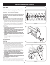
Checktheaugerdrivebeltadjustment.Withtheaugerclutchlever
in the disengaged position, the top surface of the new belt should be
even with the outside diameter of the pulley.
Toadjust,disconnectferrulefrombrakebracketassembly.Thread
ferrulein(towardsidler)toincreasetensiononbelt,orouttodecrease
belt tension.
NOTE: The brake puck must always be firmly seated in the pulley
groove when auger control is disengaged.
IMPORTANT:Repeatthe“AugerDriveControlTest”fromtheAs-
sembly section before operating snow thrower.
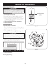
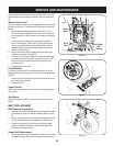
Drive Belt Replacement
Ifnotalreadydone,removetheaugerdrivebeltfromthefrontpulleyof
theenginedoublepulley.Referto“AugerBeltReplacement”instruc-
tions in the previous sub-section.
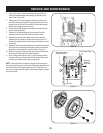
1. a. Pull the idler pulley away from the backside of the drive belt to
relieve the tension. See Figure 30.
b. Slip the drive belt off the idler pulley. Carefully release the idler
pulley.
2. Roll the drive belt off the lower drive pulley.
3. Remove the belt from the engine pulley.
4.Installthenewbeltonthepulleysinthereverseorderand
re-tension with the idler pulley.
5. Reassemble by performing the previous steps in the opposite
order and manner of removal.
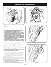
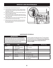
CHANGING FRICTION WHEEL
Therubberonthefrictionwheelissubjecttowearandshouldbe
checked periodically. Replace the friction wheel if any signs of wear or
cracking are found.
Run the unit’s fuel tank dry before performing Step 2.1.
Tip the snow thrower up and forward, so that it rests on the 2.
housing.
Remove screws from the frame cover underneath the snow 3.
thrower(refertoFigure31).Removetherightwheelfromtheaxle.
Figure 28
Figure 29
A
C
B
Pulley Slot
Adapter Post
Figure 30
2
3
1a
1b