


11
ASSEMBLY
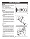
Ifadjustingtheaugercable,threadthelocknutdownthecoupler4.
towards the end of the thread to lengthen the cable as necessary
to stop the auger from turning when the control is released.
Reattach the spring to the 5. rearmost hole in the actuator bracket.
Repeat the wheel drive and auger control tests to verify proper 6.
adjustment.Repeatpreviousstepsifnecessarytoattainproper
adjustmentofeachcable.
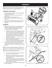
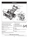
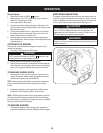
Testing Auger Drive Control
Whentheaugercontrolisreleasedandinthedisengaged“up”posi-
tion, the cable should have very little slack, but should NOT be tight.
Refer to Fig. 9 for location of controls.
Inawell-ventilatedarea,startthesnowthrowerengineas1.
instructed in the Operation section.
Whilestandingintheoperator’sposition(behindthesnow2.
thrower),engagetheaugercontrolandallowtheaugertoremain
engagedforapproximatelytensecondsbeforereleasingthe
auger control. Repeat this several times.
With the engine running and the auger control in the disengaged 3.
“up”position,walktothefrontofthemachine.Confirmthatthe
auger has completely stopped rotating and shows no signs of
motion.
Iftheaugershowsanysignsofrotating,immediatelyreturntothe4.
operator’s position and shut off the engine. Wait for all moving
partstostopbeforereadjustingtheaugercontrolcable.
Testing Wheel Drive Control & Speed Selector
Shift Lever
Refer to Fig. 9 for location of controls.
Movetheshiftleverintosixth(6)position.1.
With the wheel drive control released, push the snow thrower 2.
forward, then pull it back. The machine should move freely.
Engage the drive control and attempt to move the machine both 3.
forward and back, resistance should be felt.
Movetheshiftleverintothefastreverse(R2)positionandrepeat4.
the previous two steps.
Ifyouexperiencedresistancerollingtheunit,eitherwhenrepositioning
the shift lever from 6 to R2 or when attempting to move the machine
withthedrivecontrolreleased,adjustthedrivecontrolimmediately.
SeeAdjustingDriveandAugerControls.
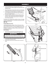
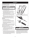
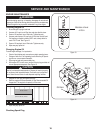
Adjusting Wheel Drive & Auger Controls
From beneath the handle, pull downward on the appropriate cable 1.
and unhook the spring found on the end of the cable from its
respective actuator bracket. Refer to Fig. 9 and 10.
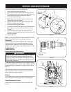
Slidethespringupthecabletoexposethecablecouplerthreads2.
and lock nut. Refer to Fig. 11.
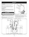
Ifadjustingthedrivecable,threadthelocknutoutward(downthe3.
couplertowardstheendfothethread)tolengthenthecableand
allow the unit to move freely when the control is released. Thread
thelocknutinward(upthecouplertowardsthecable)toshorten
the cable to reduce slippage and prevent the machine from being
easily moved with the drive control engaged.
Figure 10
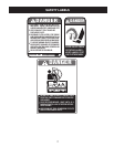
WARNING
Prior to operating your snow thrower, carefully read and follow all
instructionsbelow.Performalladjustmentstoverifyyoursnow
thrower is operating safely and properly.
Figure 11
WARNING
Do not over-tighten the cable. Over-tightening may prevent the auger
from disengaging and compromise the safety of the snow thrower.