


Hex
Nut ,.
Knob
J
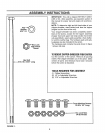
FIGURE 2,
Stop
Washer
/
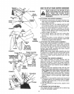
FIGURE 3.
Hopper Pivot
Door
ASSEMBLE THIS \
TRUSS SCREW
AND NUT FIRST
Release"
Bar
FIGURE 4.
FIGURE 5.
Bolt
Chute
Deflector
\ /
/
Release
Bar
8-3/8" Long
Flat Washer
Hex Lock Nut
Guide
Assembly
HOWTOSET-UPYOURCHIPPER-SHREDDER
MAKE CERTAIN THE SPARK PLUG]
WIRE IS DISCONNECTED AND MOVED /
AWAY FROM THE SPARK PLUG /
BEFORE ASSEMBLING THE CHIPPER- /
SHREDDER. j
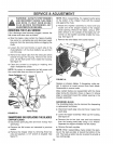
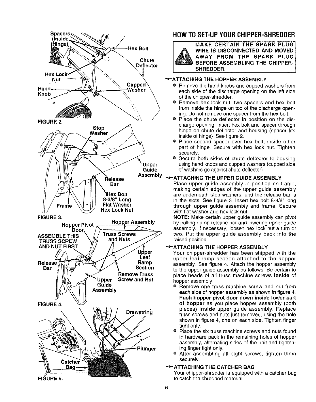
_"-ATTACHING THE HOPPER ASSEMBLY
e Remove the hand knobs and cupped washers from
each side of the discharge opening on the left side
of the chipper-shredder
e Remove hex lock nut, two spacers and hex bolt
from inside the hinge on top of the discharge open-
ing Do not remove one spacer from the hex bolt.
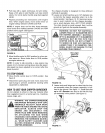
e Place the chute deflector in position on the dis-
charge opening Insert hex bolt and spacer' through
hinge on chute deflector and housing (spacer fits
inside of hinge) See figure 2.
e Place second spacer over hex bolt, inside other
part of hinge Secure with hex lock nuL Tighten
securely.
® Secure both sides of chute deflector to housing
Upper using hand knobs and cupped washers (cupped side
Guide of washers go against chute deflector)
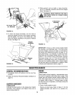
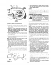
Assembly "<,-ATTACHING THE UPPER GUIDE ASSEMBLY
Place upper guide assembly in position on frame,
making certain edges of the upper guide assembly
are underrreath stop washers, and the release bar is
in the slots. See figure 3 Insert hex bolt 8-3/8" long
through upper guide assembly and frame_ Secure
with flat washer and hex lock nut
NOTE: Make certain upper guide assembly can pivot
ly by pulling up on release bar and lowering upper guide
assembly If necessary, loosen hex lock nut a turn or
two Put the upper guide assembly back into the
raised position
Leaf
Ramp
Section
Remove Truss
Screw and Nut
Drawstring
/
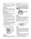
"<_-ATTACHING THE HOPPER ASSEMBLY
Your chipper-shredder has been shipped with the
upper leaf ramp section attached to the hopper
assembly. See figure 4. Attach the hopper assembly
to the upper guide assembly as follows Be certain to
place heads of all truss machine screws inside of
hopper assembly.
® Remove one truss machine screw and nut from
each side of hopper assembly as shown in figure 4.
Push hopper pivot door down inside lower part
of hopper as you place hopper assembly (both
pieces) inside upper guide assembly Replace
truss screws and nuts just removed, using the hote
shown in figure 4, one on each side. Tighten finger
tight only.
e Place the six truss machine screws and nuts found
in hardware pack in the remaining holes of hopper
assembly, alternating sides of the unit and tighten-
ing finger tight only.
® After' assembling all eight screws, tighten them
securely.
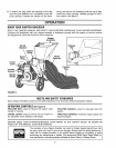
"<-ATTACHING THE CATCHER BAG
Your chipper-shredder is equipped with a catcher bag
to catch the shredded material
6