


SERVKCE & ADJUSTMENT
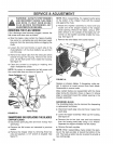
WARNING: ALWAYS STOP ENGINE
AND DISCONNECT SPARK PLUG WIRE
AND MOVE IT AWAY FROM SPARK I
PLUG BEFORE PERFORMING ANY
ADJUSTMENTS OR REPA RS.
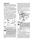
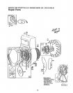
REMOVINGTHEFLAILSCREEN
If the discharge area becomes clogged, remove the
flail screen and clean area as follows
e Stop the engine, make certain the chipper-shredder
has come to a complete stop and disconnect spark
plug wire from the spark plug before unclogging the
chute
e Loosen the two hand knobs on each side of the
chute deflector Lift the chute deflector up, and tie it
out of the way
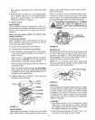
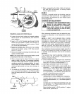
e Remove two hairpin clips from the clevis pins which
extend through the housing Remove the clevis
pins Lift the flail screen from inside the housing
See figure 18
e Clean the screen by scraping or washing with
water Reinstall the screen
NOTE: Be certain to reassemble the flail screen with
the curved side down as shown in figure 18.
Chute
Hairpin
Clips,
Clevis
Pins
_Hex
Nuts .Flail
Washers Screen
Chipper
Chute
FIGURE 18.
Hand Knobs
SHARPENINGOR REPLACINGTHE BLADES
CHIPPER BLADES
® Disconnect spark plug wire and move it away from
spark plug.
® Remove the flail screen as instructed in previous
section.
® Remove the chipper chute by removing three hex
nuts and washers A 1/2" wrench is required, See
figure 18
NOTE: When reassembling, the cupped washer goes
on the bottom of the chipper chute with the cupped
side against the chute
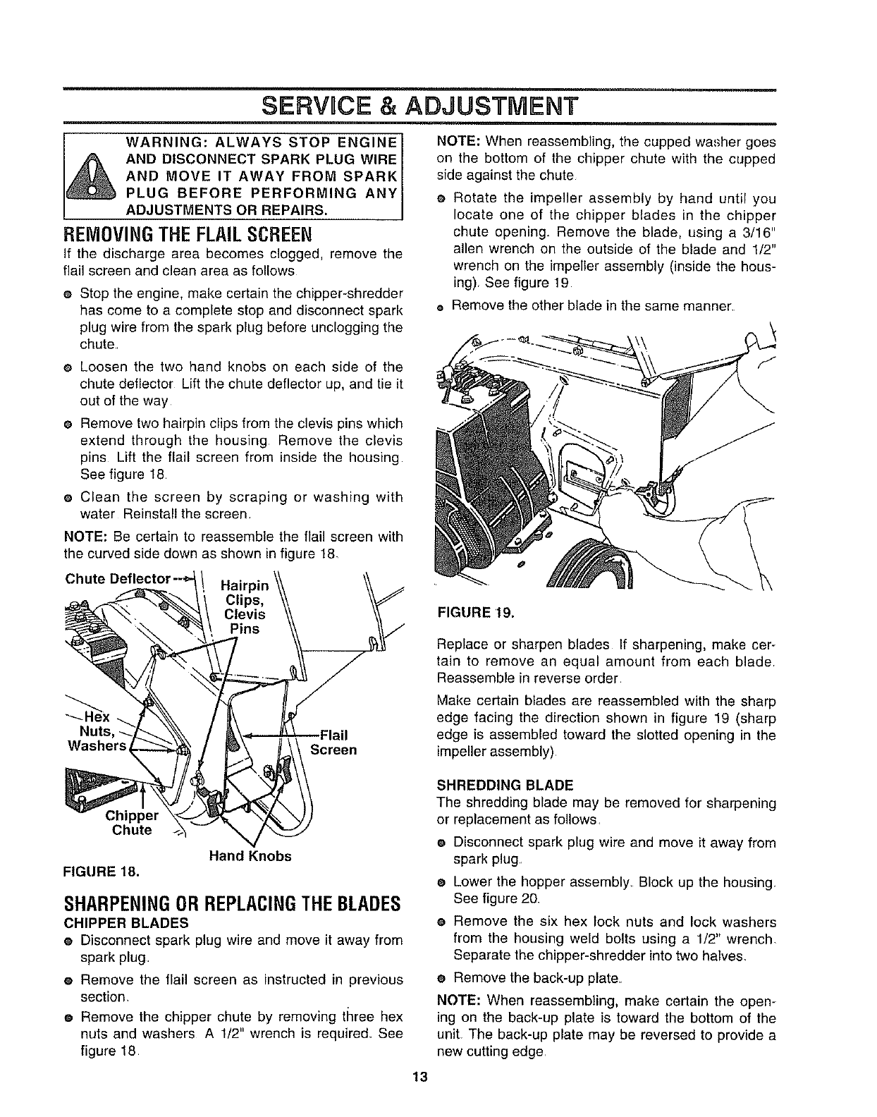
e Rotate the impeller assembly by hand until you
locate one of the chipper blades in the chipper
chute opening Remove the blade, using a 3/16"
allen wrench on the outside of the blade and 1/2"
wrench on the impeller assembly (inside the hous-
ing) See figure 19
e Remove the other blade in the same manner
@
FIGURE 19.
Replace or sharpen blades If sharpening, make cer-
tain to remove an equal amount from each blade,
Reassemble in reverse order
Make certain blades are reassembled with the sharp
edge facing the direction shown in figure 19 (sharp
edge is assembled toward the slotted opening in the
impeller assembly)
SHREDDING BLADE
The shredding blade may be removed for sharpening
or replacement as follows,
® Disconnect spark plug wire and move it away from
spark plug
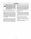
® Lower the hopper assembly, Block up the housing
See figure 20
e Remove the six hex lock nuts and lock washers
from the housing weld bolts using a 1/2" wrench.
Separate the chipper-shredder into two halves.
® Remove the back-up plate
NOTE: When reassembling, make certain the open-
ing on the back-up plate is toward the bottom of the
unit The back-up plate may be reversed to provide a
new cutting edge
13