


Finalizing System Installation
Step 1
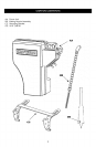
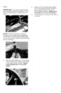
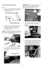
• Review the illustration below to familiarize
yourself with the suggested locations of
the routing clips (G)
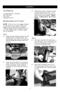
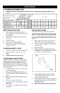
EACH SIDE OF DASH SUPPORT
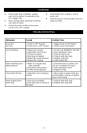
IMPORTANT: Do not kink hoses exiting the
power unit. Leave enough excess for a
generous bend in the supply lines when
assembling clip to tractor,
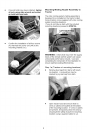
FRAME IN WHEEL WELL
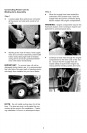
Install the three (3) routing clips (G) along
the length of the supply tubes at the
locations shown above. See further
instructions below.
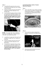
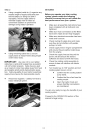
NOTE: Once the clip is installed to the supply
line, it may be slid along length of supply line to
ensure proper attachment to tractor.
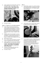
Continue mounting the next clip to the
dash support on the right side of the
tractor.
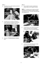
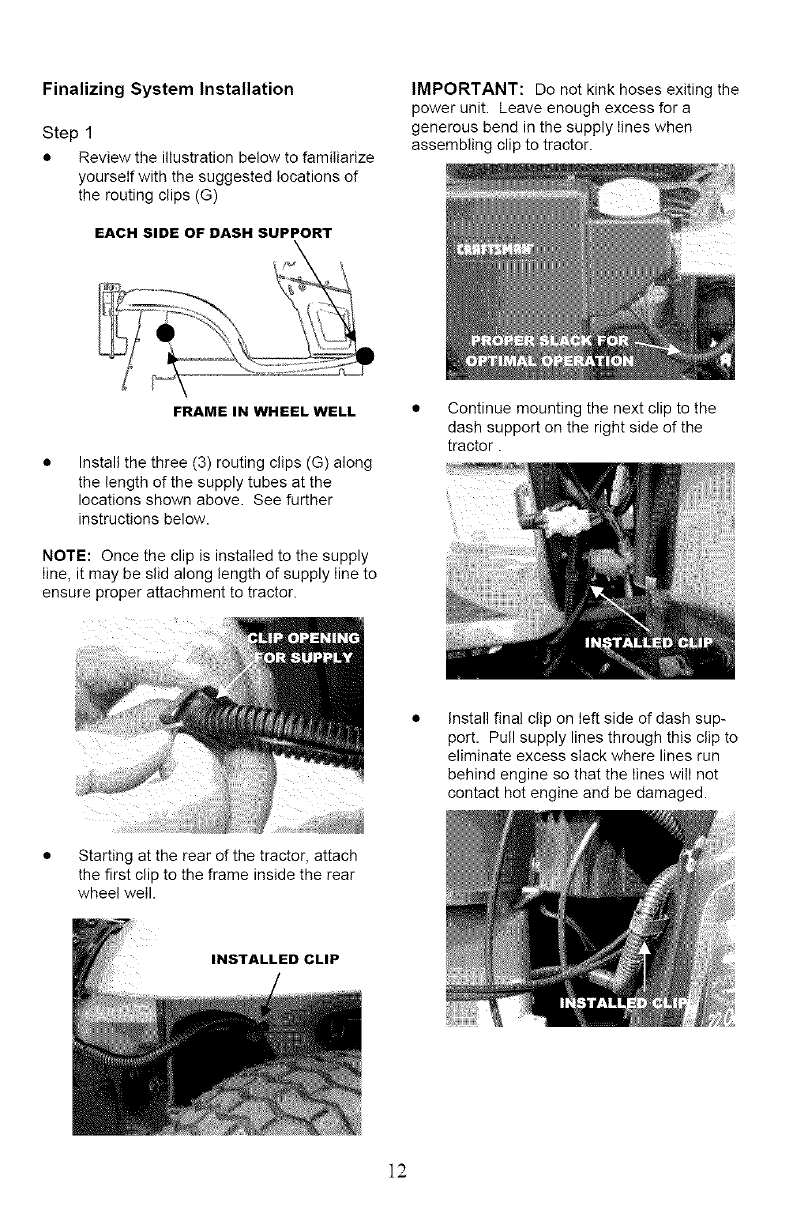
Install fin!l clip on left side of dash sup-
port. Pull supply lines through this clip to
eliminate excess slack where lines run
behind engine so that the lines will not
contact hot engine and be damaged.
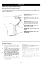
• Starting at the rear of the tractor, attach
the first clip to the frame inside the rear
wheel well.
INSTALLED CLIP
]2