


21
NOTE: The center ring sticker need not ever be removed
from the primary mirror. Because it lies directly in the
shadow of the secondary mirror, its presence in no way
adversely affects the optical performance of the telescope
or the image quality. That might seem counter-intuitive,
but it’s true!
Collimating the StarSeeker 114mm
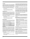
Adjustments to the collimation of the telescope can be made
by turning the collimation adjustment knobs located at the
rear of the optical tube (Figure 6-2). First loosen the three
Phillips head screws on the rear cell of the tube. Turn each
collimation knob, one at a time, until the reflected image of the
collimating cap’s dot in the secondary mirror is centered in the
primary mirror center mark ring. Once the telescope is col-
limated, tighten the Phillips head screws until you feel a slight
resistance. Do not over tighten the screws.
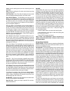
Collimating the StarSeeker 130mm
To perform collimation adjustments, the rear cover plate must
first be removed. This is done by unthreading the three small
Phillips-head screws on the back of the mirror cell (Figure
6-3). Once the cover plate is removed, the collimation adjust-
ment screws are accessible (Figure 6-4).
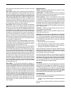
Collimation adjustments are made by adjusting the three pairs
of collimation screws (Figure 6-4). The collimation screws can
be turned with a Phillips head screwdriver and a 2.5mm hex
key. Each pair of collimation screws work together to adjust the
alignment of the primary mirror; one screw must be loosened
and the other tightened by the same amount. Try tighten-
ing and loosening one of the pairs of collimation screws by
one turn. Look into the focuser to see if the secondary mirror
reflection has moved closer to the center of the primary mirror
reflection. The collimating cap makes this easy to see; watch
if the “dot” of the collimating cap is moving closer or farther
away from the ring on the center of the primary mirror. Repeat
this process on the other two pairs of collimation screws, if
necessary. It will take a little trial and error to get a feel for
how to adjust the screw pairs to center the dot of the collimat-
ing cap in the ring of the primary mirror mark. Once the dot is
centered in the ring, the telescope is collimated, and the rear
cover plate can be reinstalled on the back of the mirror cell.
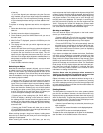
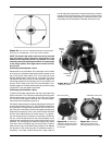
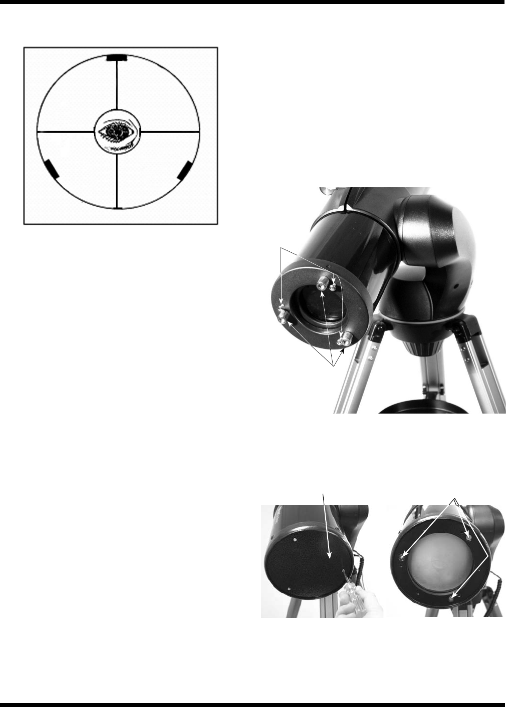
Figure 6-1. The view of a collimated telescope as seen through
the focuser of the StarSeeker 114mm and 130mm reflectors.
Figure 6-2. Collimation adjustment screws for the StarSeeker
114mm and 130mm.
Collimation
screws
Support
screws
Figure 6-3. To access the
collimation adjustment screws,
the rear cover plate must first
be removed.
Figure 6-4. Collimation
adjusted by tightening and
loosening each pair of screws.
Collimation screw pairs
Rear cover plate