


10
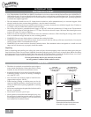
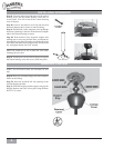
The wall control installs in the same manner as an ordinary light switch, using an existing wall box and wiring. This controller
is designed to signal the fan microcomputer as well as perform normal switching operations. For this reason the following
precautions must be observed:
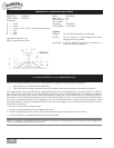
INSTALLING THE W-32 WALL CONTROL
INTELI•TOUCH
™
CONTROL INSTALLATION
INTELI•TOUCH
™
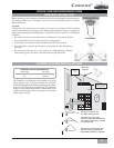
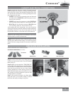
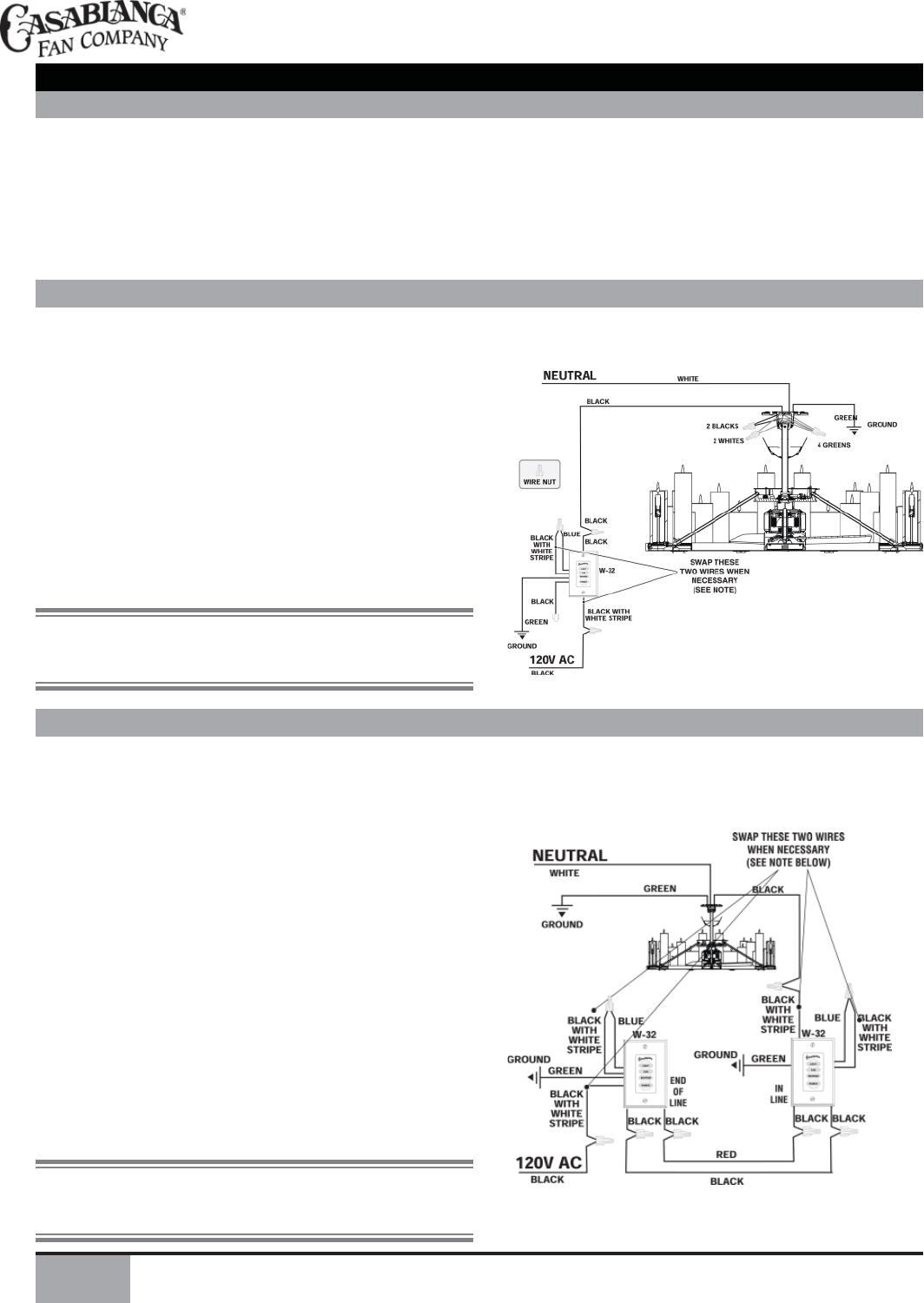
SINGLE W-32 INSTALLATION
W-32 is used to describe either white (-11) or ivory fi nish.
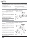
1. Remove the screws and switch plate from the existing switch box.
2. Remove the screws holding the switch in the switch box.
3. Pull the existing switch from the switch box to expose the wire
connections.
4. Remove the two wires from the switch.
5. Connect the two wires just removed from the switch to the W-32 wall control
black wire and black/white stripe wire. Secure these connections with wire
nuts.
6. Connect the green ground wire coming from the back of the W-32 control
to the ground wire in the switch box. Secure the splice with wire nut.
7. Install the W-32 in the wall box with the two long screws provided.
8. Install the wall plate with the two color matched screws.
1. Use only the Casablanca W-32 wall control.
2. Do not use any additional control with your Inteli-Touch fan
(for example, dimmer, fan speed control, etc.).
3. Do not use more than one fan per wall control.
4. No other light fi xtures or electrical appliances may be
connected on the circuit controlled by the W-32 wall
control.
CAUTION!
Ensure power is turned OFF at the breaker or fuse panel before starting installation.
NOTE: If wall control operation is reversed (fan switch controls lights and
light switch controls fan) turnoff the power at the breaker or fuse panel, then
swap the two W-32 black/white stripe wires.
INTELI•TOUCH
™
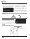
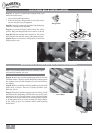
DUAL W-32 INSTALLATION
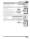
To control the fan and lights from two locations (a three-way circuit), use 2
W-32 wall controls.
1. Remove the screws and switch plate from the existing switch box and the
screws holding the switch in the switch box.
2. Pull the existing switch from the switch box to expose the wire
connections.
3 Determine which wire is connected to the common terminal of the 3-way
switch. (The terminal will be marked on switch).
4. Remove the wire from the common terminal of the 3-way switch. Connect
this wire to the remaining black/white striped wire on the W-32 control.
Secure this splice with a wire nut.
5. Remove the two remaining wires from the 3-way switch. Connect one of
these wires to a black wire on the W-32 control. Secure the splice with a
wire nut. The remaining wire is to be connected to the other black wire on
the W-32.Secure the splice with a wire nut.
6. Connect the green ground wire coming from the back of the W-32 control
to the ground wire in the switch box. Secure the splice with a wire nut.
7. Install the W-32 in the wall box with the two long screws provided.
8. Install the wall plate with the two short color-matched screws provided.
9. Installation of the second W-32 control is identical. Repeat steps 1 through 7.
NOTE: If wall control operation is reversed (fan switch controls lights and
light switch controls fan) turn off the power at the breaker or fuse panel, then
swap the two W-32 black/white stripe wires.
CAUTION!
Ensure power is turned OFF at the breaker or fuse panel before starting installation.