2-- 4
T -343
2.4 CONTROL CIRCUIT OPERATION
WARNING
Beware of moving poly V-Belt and belt driv-
en components.
2.4.1 Sequence of Operation
a. Standard Units
With the i ntake heater switch (IH) held in the ON
position, current flows through the ammeter to the
intake heater. While heat er ison, the ammeter will show
a 40--amp draw.
A second set o f contacts also energizes the safety relay
(S).
If the high water temperature switch (HWT) opens to
break the safety relay ground connection, the safety
relay will not energize, and the engine will not start,
To start the engine, the ignition switch (IGN) is held in
the STAR T position. With the switch in the ST ART
position, current flows tothe startsolenoid (SS),through
the SS contacts to the starter motor (SM). Current then
flows totheintake heatertimer ,intakeheater r elay(IHR)
and to the heater , while simultaneously powering the
electronic governor module (EG), fuel solenoid ( FS),
and engine speed sensor (ESS).
The starter motor turns over the engine resulting in
pumping of fuel to the engine cylinders by the injection
pump. This fuel is ignited by heat of compression; thus
starting the engine. When the engine has developed
sufficient oil pressure, the low oil pressure switch
contacts close to maintain power to the safety relay.
Once the engine has started, the intake heater will
remain energized for 3 minutes.
The ignition switch (IGN) will be released. The intake air
heater switch (IH) will be held for 5 seconds, then
released after the IGN switch is realeased. When the
STAR T switch is released, the starter will be
disengaged.
With the engine running, the battery charger provides
DC power to operate the control system and charge the
battery.
b. Units with Auto Start
When the ignition switch is placed in the RUN position,
12-volt DC power is applied to the low coolant sensor
(LCS) and the auto restart modulesimultaneously. Ifthe
coolant level is below the sensor, all the indicator lights
on the auto restart module will blink once and the LCS
will open the contacts on the low coolant relay,
de-energizing the unit’ s 12-volt DC circuitry. If the
coolant level is above the sensor, the auto restart
module will maintain power and all lights on the module
will illuminate. As the module performs its self test, the
lights will go out individually.
After the self test is complete, the module will energize
the intake heater and sound the audible alarm warning,
indicating that the unit has been powered on and will
start. The 3 0--second delay starts at this time. Whenthe
30--second delay expires, power will be applied to the
electronic governor andtheengine attempts to crankfor
15 seconds.
When the engine starts, the intake heater will remain
energized for 3 minutes; during this time, the
engine/intake heater light and alarm will be energized,
the shutdown/lockout time delay of 15 seconds will
begin counting, and the starter will be disengaged.
During the shutdown/lockout time delay at start up, the
auto restart module will disregard the signals to the oil
pressure and engine temperature inputs, and the Run
sequence will begin (see Restart Procedure). If engine
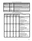
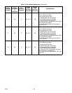
does not start, refer to Table 1.3 for auto restart
sequencing.


