


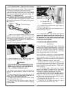
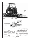
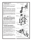

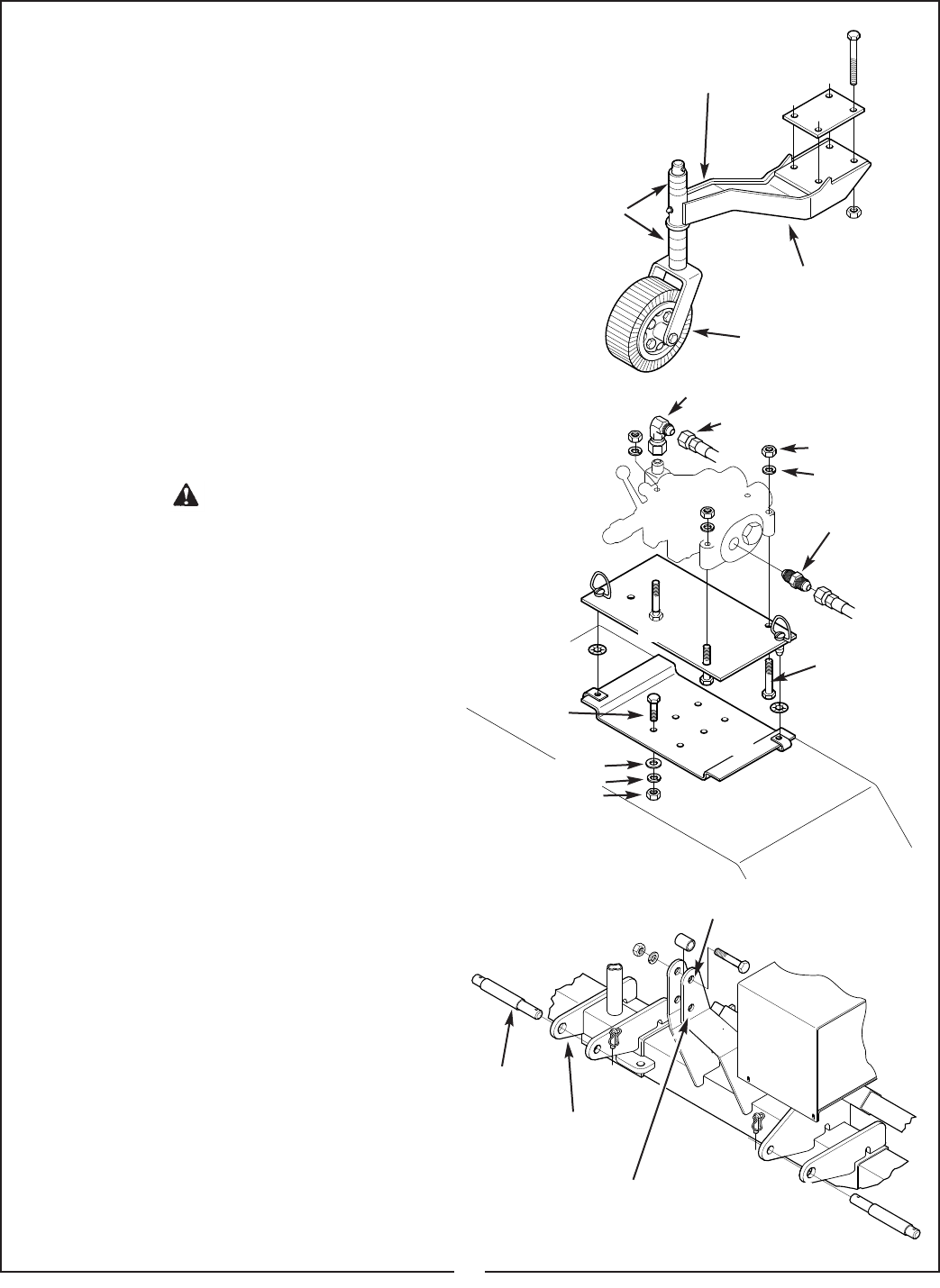
5-5 OPTIONAL TAILWHEEL
INSTALLATION
A. Position mounting bracket against underside of
frame as shown. (Fig. 5-6)
B. Position mounting plate on top side of frame
and fasten with four 5/8 x 7-1/2” bolts and locknuts.
C. Apply warning decal to top of tailwheel beam.
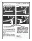
ADJUSTMENT
The tailwheel is adjustable in one inch increments
using collars on tailwheel spindle. To adjust, raise
cutter and securely block in position. While holding
wheel, remove pin from spindle. Remove wheel
assembly from mounting bracket. Stack spacers on
spindle as necessary to achieve desired height.
Large spacers are two inches, small spacers are one
inch.
Slide spindle back into bracket placing remaining
collars on top of spindle. Install retaining pin. Note
that any change in tailwheel height should be fol-
lowed by a 3-point hitch top link adjustment to keep
cutter level.
TAILWHEEL IS NOT TO BE USED TO SUP-
PORT CUTTER AT TRANSPORT SPEEDS.
MAXIMUM SPEED FOR TAILWHEEL IS 6
MPH. EXCEEDING THIS SPEED COULD
CAUSE EQUIPMENT FAILURE WITH
POSSIBLE INJURY TO OPERATOR.
Note that when cutter is equipped with both side-
wheel and tailwheel, the adjustment of one can
affect adjustment of the other. If the cutting height is
higher than 4 inches, cutter must be totally support-
ed by tractor 3-point lift. When cutting a ditch or
bank, sidewheel and tailwheel can be adjusted inde-
pendently as needed.
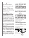
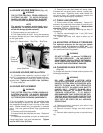
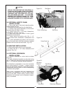
5-6 OPTIONAL VALVE MOUNTING
BRACKET INSTALLATION
(Fig. 5-7)
A. Place bottom bracket at desired mounting loca-
tion. Mark 2-4 holes (as needed) for drilling using
bracket as pattern. Drill holes using 13/32 drill bit.
B. Mount lower bracket using four 3/8 x 1-1/2”
bolts, nuts, flatwashers and lockwashers.
C. Attach valve to top bracket using three 3/8” x 2-
1/2” bolts, nuts and lockwashers.
D. Mount top bracket to bottom bracket using
quarter turn fasteners. Insert quarter turn fastener
into clip-on receptacle and turn 90 degrees.
E. Install hydraulic fittings as shown in Fig. 5-7 (if
necessary).
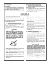
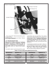
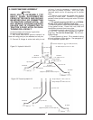
5-7 HITCH PIN ORIENTATION (Fig. 5-8)
Insert lower hitch pins through hitch lugs on frame
according to category hitch of your tractor. Locate
bolt and bushing as shown in illustration.
19
Hitch Pin
Hitch Lugs
Figure 5-8 Hitch Cat. III Quick Hitch Location
Disconnect Hose and Install this 90° Adaptor. Reconnect Hose
3/4” JIC Female to 3/4” JIC Male
To Source
3/8” Hex Nut
3/8” Lockwasher
Remove 90° Elbow &
Install Straight Adaptor
7/8” ORB x 3/4” JIC
Figure 5-7
Valve Mounting
To Source
3/8” x 2-1/2”
Capscrew
(3 Furnished)
Valve Plate
Base Plate
Tractor Fender
3/8” x 1-1/2”
Capscrew
3/8” Flatwasher
3/8” Lockwasher
3/8” Hex Nut
Figure 5-6 Tailwheel Assembly
Apply Decal
Mounting Bracket
Tailwheel
Spacer Collars
Cat. II Quick Hitch and
Cat. II Standard Hitch Bushing Location
WARNING