


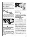
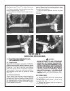
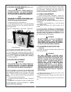
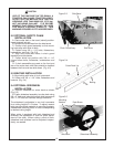
4-4 BLADE HOLDER REMOVAL (Fig. 4-3)
THE CUTTER CAN FALL FROM HYDRAULIC
SYSTEM FAILURE. TO AVOID SERIOUS
INJURY OR DEATH, SECURELY SUPPORT
CUTTER BEFORE WORKING UNDERNEATH.
NOTE
The spindle is a straight splined shaft, not a
tapered shaft. Do not hit on end of spindle shaft
as this will damage spindle assembly.
A. Remove cotter pin and castle nut.
B. Pull blade holder off shaft. It may be necessary
to remove blades and pan, then remove blade hold-
er with gear puller.
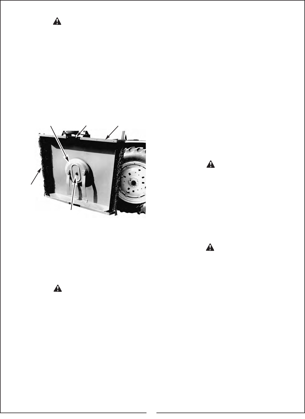
Figure 4-3 Blade Holder Skid Filler Skid Shoe
4-5 BLADE HOLDER INSTALLATION
A. If blades were removed, perform steps “C”
and “D” in paragraph 4-6 to reinstall blades and pan.
B. Assemble blade holder and castle nut onto
spindle shaft. Tighten nut to 300 ft./lbs. (406 Nm).
C. Insert cotter pin.
4-6 BLADE REPLACEMENT
THE CUTTER CAN FALL FROM HYDRAULIC
SYSTEM FAILURE. TO AVOID SERIOUS
INJURY OR DEATH, SECURELY SUPPORT
CUTTER BEFORE WORKING UNDERNEATH.
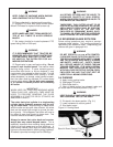
It is not necessary to remove the complete blade
holder assembly to replace the blades. Blade bolts
are accessible through a hole in the top of the cutter
deck. Blades should only be replaced in matched
pairs. Use only genuine Bush Hog replacements
parts.
A. Remove nuts from blade bolts.
B. Inspect blade bolt shoulder for wear. Replace if
necessary.
C. Assemble new blades and pan to blade holder
using blade bolts, nuts and lockwashers. Tighten
nuts to 450 ft./lbs. (610 Nm).
D. Check to be sure that blades will swing freely.
If blades will not swing freely, remove, locate prob-
lem, and repair. Operating cutter when blades will
not swing freely will cause excessive stress and
vibration causing damage to implement.
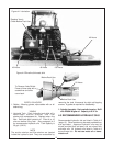
4-7 CABLE ADJUSTMENT
A. Extend slide cylinder completely. Assure full
extension by measuring from center of mounting pin
to center of opposite mounting pin. Measurement
should be 72-3/4 in. (1847.8 mm).
B. Put slack into cables by loosening eye bolts (if
necessary).
C. Position counterweight box 1 inch (25.4 mm)
from hydraulic tank.
D. Tighten eye bolts until slack is taken out of
cables.
4-8 ADJUSTING HYDRAULIC PRESSURE
The hydraulic pressure for the cast iron system
is preset from the factory at 3200 psi. If a
hydraulic pressure adjustment is necessary, contact
your authorized Bush Hog dealer.
DO NOT ATTEMPT TO ADJUST HYDRAULIC
SYSTEM PRESSURE. AN INCORRECT
ADJUSTMENT COULD CREATE EXTREMELY
HIGH PRESSURES RESULTING IN PERSON-
AL INJURY AND EQUIPMENT DAMAGE.
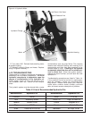
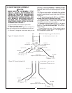
4-9 CHANGING BLADE ROTATION
(Fig. 4-4)
To change the direction of blade rotation perform the
following procedures:
DO NOT OPERATE CUTTER WITH
COUNTERCLOCKWISE BLADE ROTATION
UNLESS CUTTER DECK IS EQUIPPED WITH
SAFETY CHAINS AND THE OPERATOR
WEARS SAFETY GLASSES AND SAFETY
(HARD) HAT. SAFETY CHAINS WILL
REDUCE AMOUNT OF DEBRIS THROWN
TOWARD OPERATOR. IT IS HIGHLY
RECOMMENDED THAT OPERATOR BE PRO-
TECTED WITH ROLLOVER PROTECTIVE
SYSTEM (ROPS) ENCLOSED CAB AND THAT
SEAT BELT BE USED FOR ALL MOWING
OPERATIONS.
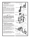
A. Remove hydraulic pressure and return lines
from connections on motor.
B. Remove hydraulic fittings from both sides of
motor.
C. Remove bolts retaining motor to spindle hous-
ing.
Chain
Guard
Assembly
Lower Shaft Nut
13
WARNING
WARNING
WARNING
WARNING