


8
26-7/8”
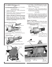
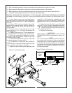
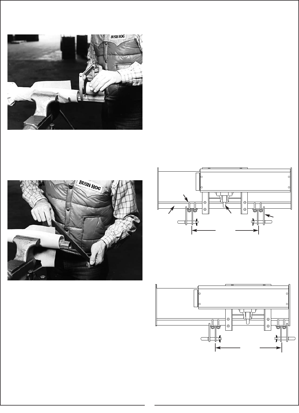
Figure 2-7 Alternate Hitch Lug Mounting
Figure 2-6 Hitch Lug Dimension
Clamp
Bolts
Frame
Hitch Pin
Brackets
Gearbox
Input Shaft
26-7/8”
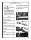
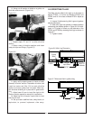
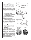
H. Using cut off section of shield as a guide, cut
shaft the same amount. (Figure 2-4)
Figure 2-4
I. Repeat steps “G” and “H” to other driveline
section.
J. Deburr ends of driveline sections and clean
away all chips and fillings. (Figure 2-5)
Figure 2-5
K. Apply multi-purpose grease to inside of outer
(female) driveline section. Assemble driveline and
install on tractor and tiller. Pull on each driveline
section to be sure yokes lock into place. Make cer-
tain driveline shielding is in place and in good condi-
tion.
L. Adjust lower lift arm to level tiller right to left.
Refer to tractor operator’s manual for instructions.
M. Adjust top link of tractor 3-point hitch to level
tiller front to rear.
N. Set up tractor stabilizer bars, sway blocks, or
equivalent to prevent implement side sway.
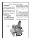
2-2 OFFSETTING TILLER
The tillers may be offset to the right up to 6 inches on
Model RTS40, 12 inches on Models RTS50 and
RTS60, and 18-1/4 inches on Model RTS74. Adjust as
follows:
A. Loosen U-bolts securing hitch lugs and gearbox
stand to tiller frame.
B. Slide hitch lugs and gearbox to desired position
maintaining the distance shown in Figure 2-6. An addi-
tional 4-1/2 inches of offset can be obtained on the
RTS40 and RTS50 by reversing hitch lugs as shown in
Figure 2-7.
C. Tighten U-bolts.