16
White
Red (To Starter)
Green
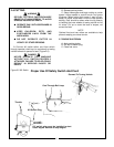
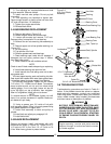
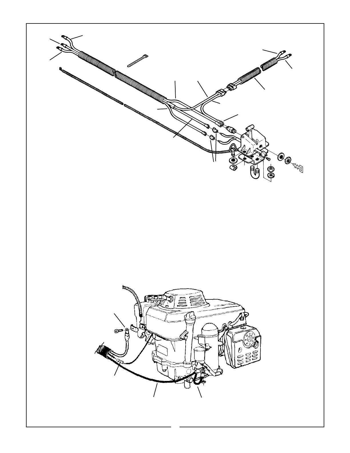
Figure 4-2 Wiring Diagram
Red White
Green
Orange
To Safety
Kill Switch
Red
To Key Switch
Battery Pigtail
To Battery
White
Red
-
+
4-2 ELECTRIC START CONNECTION
TO ENGINE
NOTE
To mount control on ATV, see paragraph 2-4.
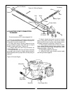
A. Cut ring connector from engine end of green
wire in cutter wiring harness. (Figure 4-2) Strip 1/4”
of insulation from end of green wire.
B. Using butt splice, connect green wire from
wiring harness to green wire lead next to engine
throttle, crimping with pliers. (Figure 4-3)
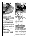
C. Attach white wire with loop connector as
shown in Figure 4-3.
D. Attach red wire with loop connector and short
red jumper wire to post on engine starter solenoid.
Attach opposite end of jumper wire to male prong on
solenoid.
E. Attach female terminals on end of jumper
wires to key switch mounted in control box. Attach
female terminal ends on green and orange wires to
kill switch mounted in control box. (Figure 4-2)
F. Push engine throttle down to limit of travel.
Push remote throttle control to stop position. Insert
cable into throttle. Place cable housing under cable
clamp and tighten. (Figure 4-3)
G. Plug battery pigtail into harness.
H. Using wire ties, strap throttle control cable
and wiring harness together.
Figure 4-3 Honda Engine
White Wire
Butt Splice
Green Wire
Red Wire
Red Jumper Wire


