12
SECTION III
MAINTENANCE
WARNING
BEFORE PERFORMING MAINTRENANCE
INSPECTIONS OR WORK ON CUTTER,
SHUT CUTTER ENGINE OFF AND DIS-
CONNECT SPARK PLUG WIRE. FAILURE
TO DO SO COULD RESULT IN ACCIDEN-
TAL STARTING OF ENGINE CAUSING
POSSIBLE INJURY OR DEATH.
3-1 MAINTENANCE CHECK LIST
Perform scheduled maintenance as outlined below.
Shut down engine, disconnect spark plug wire, and
disconnect battery pigtail harness before doing main-
tenance inspections and work. For engine mainte-
nance see Engine Owner’s Manual. All bolts should
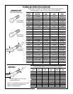
be torqued as recommended in Torque Chart unless
otherwise specified.
BEFORE EACH USE
1. Check engine oil level. Add oil as necessary per
engine owner’s manual.
2. Check engine fuel level, add as necessary. Allow
engine to cool before filling. Use only approved
funnel and container to handle gasoline. Do not
fuel tank indoors. Wipe up spilled gasoline.
3. Inspect blade belt for tightness and wear. Tighten
if necessary per paragraph 3-2.
4. Check blade for sharpness and damage. If dull,
sharpen at a 45 degree angle on a bench grinder.
Make certain blade is balanced before rein-
stalling. If blade is bent, broken, or worn out,
replace with a genuine Bush Hog replacement
blade.
5. Check blade bolts for tightness. Tighten 3/4 x
2-1/4” bolts to 297 ft./lbs. and the 1/2 x 2” bolts to
76 ft./lbs.
6. Check blade bar nut for tightness. Tighten to 750
ft./lbs.
7. Make certain the cutter deck enclosed sides are
not damaged, bent or missing. Make necessary
repairs before operating cutter.
8. Make certain belt shield is in place and in good
condition.
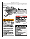
9. Clean any debris from the safety decals and
check decals for legibility. Replace any missing or
illegible decals. Read and heed the safety decal
messages.
10.During operation, listen for abnormal sounds
which might indicate loose parts, damaged bear-
ings, or other damage. Repair or replace as nec-
essary.
40 HOURS
1. Grease blade hub assembly using grease gun
and multi-purpose grease until grease purges out
top seal. Wipe away excess grease to prevent
contact with belt.
3-2 BELT ADJUSTMENT
A. Remove belt shield.
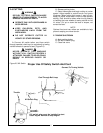
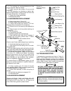
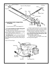
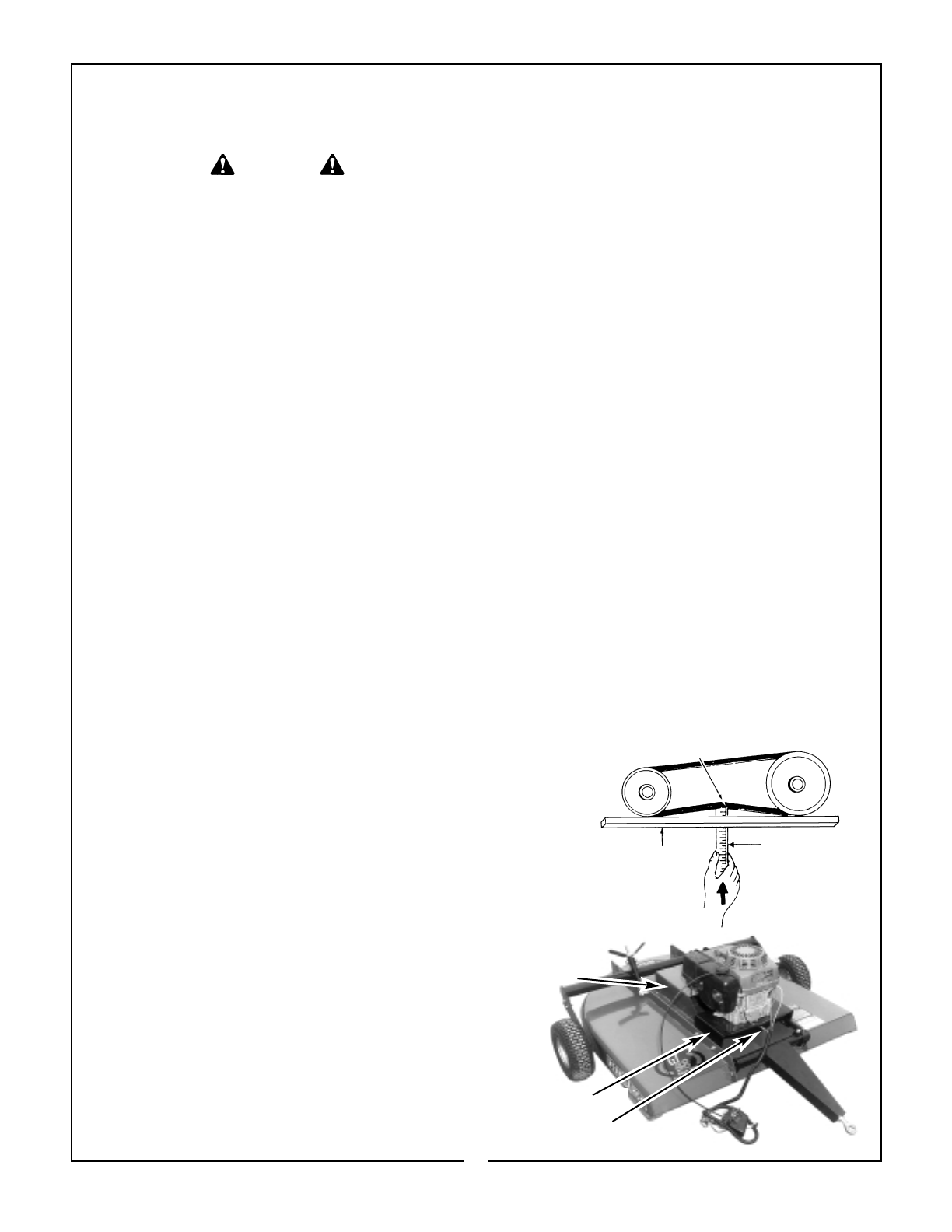
B. Check belt tension as shown in Figure 3-1. If
belt needs adjusting, proceed to step “C”. If not,
reinstall belt shield.
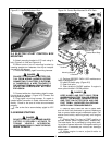
C. Loosen four bolts securing engine stand to
deck weldment. (Figure 3-2)
D. Turn adjusting bolt located at front of engine
stand clockwise to tighten belt, counterclockwise to
loosen belt. Place enough tension on belt to allow
not more than 1/2” and not less than 1/4” deflection.
(Figure 3-1) If a belt tension gauge is available, set
to 120 lbs. of tension.
E. Tighten four engine stand bolts.
F. Reinstall Shield.
3-3 REPLACING BELT
A. Remove belt shield. (Figure 3-2)
B. Loosen four bolts securing engine stand to
deck weldment.
Figure 3-1
Belt Deflection
Approximately 1/4”
Straight Edge
Ruler
4 lbs. of Force
Figure 3-2
Belt Shield
Engine Stand
Adjusting Bolt


