


Document: - page 3 (Black)
Screen angle and frequency: 45.0000, 150.0000
GB
3
ADDITIONAL COMPONENTS
FOR INSTALLATION
To complete the installation of your outboard, you will need the
following items. Your Briggs & Stratton Dealer has kits
available to aid installation. See an Authorized Briggs &
Stratton Dealer for available Power Supply Harness kits, which
include the battery harness and fuse supplies.
• Line Fuse, fuse block & cable caps. Connect fuse as
shown under Ba tte ry Installation. Use appropriate
cable caps to protect the fuse block terminals.
• Batte ry Harness. 6 gauge wire or larger, term in a tin g in
an Anderson SB120 (or equivalent) connector, to
connect the ba tterie s to the outboard.
• Deep cycle marine ba tterie s . Briggs & Stratton
recommends using four 12 Volt batteries. Refer to a
marine battery manufacturer or dealer for specific
information.
• U.S. Coast Guard approved battery boxes.
• 6 gauge wire battery cable interĆconnects.
Please re fe r to the Battery Recommendation and Battery
Installation sections fo r further informatio n on proper
batte ry connection.
OUTBOARD
INSTALLATION
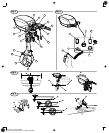
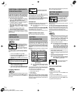
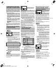
OUTBOARD PLACEMENT
Fig. 3
WARNING
When determining conformity to
boat weight limitations, take into
account the weight of the outĆ
board AND battery pack.
Follow the boat manufacturer's
recommendations to install the
outboard to the boat.
The capacity plate on the boat shows the maximum
horsepower allowable for your boat. DO NOT exceed this
limit.
1. Center the outboard Ê on the transom Ë.
2. Be sure the antiĆventilation plate Ì of the outboard is
positioned below the bottom Í of the boat.
3. Tighten the clamp screws Ï to secure the outboard to
the transom.
CAUTION: Inspect clamps periodically for tightness to
prevent engine from loosening off of transom. Do not allow
any part of motor or shaft to rub or be in contact Î with the
transom.
4. Adjust the tilt pin to obtain a vertical position for the
outboard. See Outboard Trim Angle.
5. Test the range of steering motion ¼. No part of the
gear case or propeller should contact the transom.
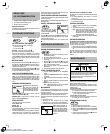
OUTBOARD TRIM ANGLE
Fig. 4
Follow the boat manufacturer's instructions for the correct trim
angle. The outboard has five trim positions Ê. The ideal trim
angle allows the antiĆventilation plate to run parallel Ë to the
water surface.
WARNING
DO NOT attempt to adjust the trim
angle while the outboard is runĆ
ning.
If the bow of the boat is above horizontal Ì put the tilt pin in a
lower adjustment hole to move the outboard closer to the
transom (example from hole A to hole B or C).
If the bow of the boat is below horizontal
Í put the tilt pin in a
higher adjustment hole to move the outboard farther from the
transom (example from hole E to hole D or C).
OUTBOARD TILT
The outboard can be tilted to gain clearance and avoid lower
unit damage when landing the boat in shallow water.
Note: The outboard cannot be locked in the UP/
TILTED position.
Tilt the outboard using ONLY the TILT/CARRY HANDLE Î at
the rear of the outboard. Pull the TILT/CARRY HANDLE in the
direction Ï as shown to tilt the outboard.
Lower the outboard slowly AFTER the boat has come to rest.
REMOTE CONTROL INSTALLATION
Refer to instructions included with remote steer kit.
BATTERY
RECOMMENDATION
The outboard requires a 48 volt power source. For best results,
use marine group 31 deep cycle batteries with at least 100
ampere hour rating. Your outboard can draw 70 amps
continuously with the throttle set at MAX POWER, and as
much as 100 amps for short periods of time. The actual ampere
draw is subject to your particular environmental and operating
conditions.
Refer to a marine battery manufacturer or dealer for specific
information.
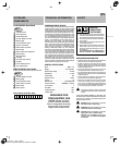
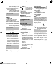
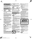
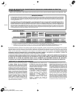
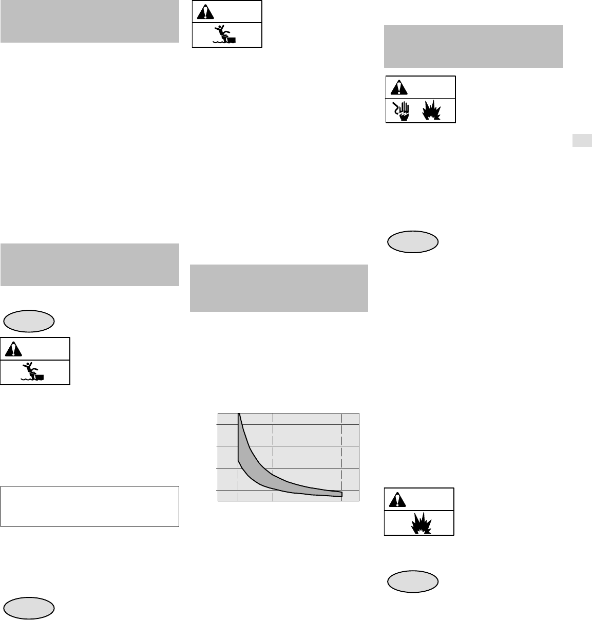
Troll MaximumCruise
8
7
6
5
4
3
2
1
0
Typical Run Time vs Speed Setting
Run Time (hrs)
Speed Setting
Note: Run time and speed will vary based on battery
size, boat hull size, type and loading, and water
conditions.
Cycling batteries are designed to have good life performance
in deep cycle service. The major cause of battery failure in
deep cycle service is poor maintenance:
• Dirt and co rro sio n on battery tops or terminals
• Incorre ct battery water level
• Lack of charging
• Excessive discharge
Maintain battery pack at full charge. Proper care will signifiĆ
cantly improve the battery life. Failure to properly recharge
batteries (within 12Ć24 hours) may cause reduced battery
performance or premature battery failure. For best results, use
a variable rate charger.
Refer to the battery charger manufacturer for specific informaĆ
tion on how to charge the battery pack.
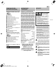
BATTERY HARNESS
INSTALLATION
WARNING
Risk of Electrical Shock. DO NOT
touch unĆinsulated battery termiĆ
nals, connectors, or wires.
Prior to wiring the batteries, enĆ
sure that the battery harness is
unplugged from the outboard.
Batteries must be connected in series to obtain 48 volts with
100 ampere rating.
You need to purchase three 6Ćgauge battery cable inter conĆ
nects. The battery connection diagram is for reference ONLY.
While the connections will follow the pattern as shown, the acĆ
tual position of the batteries may vary depending upon how
and where the batteries are located within your boat.
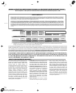
Use the following procedure and follow diagram to harness the
batteries.
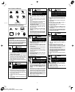
Fig. 5
1. Using a separate interconnect for each battery, connect
the positive(+) lead from one battery to the negative(-)
lead on the next battery. The batteries will then be
connected in series, with a single positive(+) and
negative(-) lead left open at each end of series.
2. Tighten the battery terminals to 130 lbĆin (15 Nm), or as
specified by the battery manufacturer.
Note: This outboard is equipped with an AndersonR
connection Ê terminal. The line fuse Ë is loĆ
cated on the positive (+) lead side. Connect the
positive (+) lead to the o pen positive terminal of
the battery series. Connect the negative (-) lead
to the open negativ e terminal of the battery series.
3. Connect the positive(+) lead of the battery harness to
the open positive(+) battery terminal.
4. Recheck all connections to ensure they match the wiring
diagram prior to plugging the battery harness into the
outboard.
5. Keep wire connections to the batteries tight, maintaining
good contact with the battery terminals.
Note: The battery connection diagram is for reference
ONLY. It depicts four 12 volt batteries wired in a
series to produce a total of 48 volts.
WARNING
Improper wiring of batteries could
cause batteries to explode.
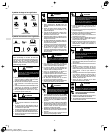
FUSE BLOCK CONNECTIONS
Fig. 6
• Remove Fu se Block Cover Ê.
• Remove cable mounting scre w and nu t Ë fro m blo ck
termin a l.
• Attach fu se lin k cable Ì to terminal.
• Repeat, attach in g the harness lead to other terminal.
• Before tightening cable scre w s, slide fuse Í into block.
• Tighten screws and replace co ve r.