


Document: - page 1 (Black)
Screen angle and frequency: 45.0000, 150.0000
GB
GB
1
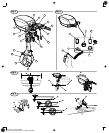
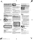
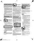
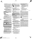
OUTBOARD
COMPONENTS
TILLER CONTROL Model AA0201
Fig. 1
1
Transom bracket
2
Power receptacle
3
Serial number label
4
On / Off / Batter y test switch
5
Battery gauge
6
Forward / Reverse switch
7
Support / front handle
8
Safety / Motor stop switch
9
Speed control
10
Speed control friction adjustment
11
Safety lanyard
12
Mounting clamps
13
Vent plug
14
Gear case drain / fill plug
15
Propeller
16
ThrustĆenhancing nozzle
17
AntiĆventilation plate
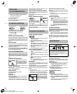
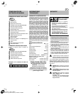
REMOTE CONTROL Model AA0202
Includes above components with exceptions noted below:
Fig. 2
4
On / Off / Battery test sw itch
5
Battery gauge
6
Forward / Reverse switch
7
Safety / Motor stop switch
8
Speed control
9
Safety lanyard
Record Unit Serial No. Here
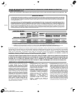
TECHNICAL INFORMATION
POWER AND THRUST RATINGS
The power ratings for an individual electric outboard model are
initially developed by starting with those provisions of SAE
(Society of Automotive Engineers) Surface Vehicle Standard
J1228 (Small Craft ć Marine Propulsion Engine and Systems ć
Power Measurements and Declarations) (Revision Nov. 1991)
that are relevant to electrically powered outboard units, such
as sections defining measurement of declared (rated) power
(3.2), and establishing manufacturing tolerance (4.1.1 & 8).
The source of electrical power is a fully charged battery pack,
similar to and representative of that typically used in the
application; high current cabling is per ABYC guidelines.
Electrical measurements are performed by generally accepted
means. Thrust tests are direct force measurements, taken at
stall, on open water. Peak thrust is quoted instead of peak
power; the intent of the design is to maximize thrust and
efficiency at displacement speeds. The 3150" designation
means that the nominal fullĆcharge continuous power rating is
3 hp, and the nominal peak developed thrust is 150 lb
f
. Actual
on site" power and/or thrust developed may differ from the
nominal rated values, due to several factors: Selection of and
stateĆofĆcharge of the propulsion batteries; changes in temperĆ
ature; individual unitĆtoĆunit variation; mode of operation --
acceleration or cruise; mass, type, and length of craft to which
the outboard is fitted; the presence of wind, weeds, and water
currents; as well as any other factors which may reasonably be
inferred to influence the performance of the unit.
GENERAL SPECIFICATIONS
Motor Etekt D.C.. . . . . . . . . . . . . . . . . . . . . . . .
Weight 27.2 kg (60 lbs.). . . . . . . . . . . . . . . . . . . .
Nominal Input Voltage 48 VDC. . . . . . . . . . . . . . .
RPM Range 0 - 3400. . . . . . . . . . . . . . . . . . . . . .
Power Rating 3 hp. . . . .
. . . . . . . . . . . . . . . . . . .
Maximum Thrust 150 lbs. . . . . . . . . . . . . . . . . . . .
Cooling Air. . . . . . . .
. . . . . . . . . . . . . . . . . . . . . .
Motor Control Forward/Reverse. . . . . . . . . . . . . . .
Power Connection AndersonR 120 amp. . . . . . .
.
Trim Positions 5. . . . . . . . . . . . . . . . . . . . . . . . . .
Gear Ratio 1.57/1. . . . . . . . . . . . . . . . . . . .
. . . .
Propeller Diameter 7.8 in.. . . . . . . . . . . . . . . . . . .
Propeller Pitch 7.8 in.. . . . . . . . . . . . . . . . . . . . . .
.
CAUTION: Saltwater is extremely
corrosive to outboard components.
Failure or damage related to salt water
corrosion is NOT covered under the
Briggs & Stratton limited warranty.
DESIGNED FOR
FRESHWATER USE
SAFETY
• Every operator should read and understand the
entire Operating & Maintenance Instructions AND
the instru ctio n s for the boat this outboard pow e rs.
• Failu re to follow instructions could result in serious
injury or death.
• Use the sa fety and operating instructio n s to help
avoid damage and injury.
• Briggs & Stratton recommends the completion of a
boater
safety course. Contact the U.S. Coast
Guard or the appropriate state agency. For more
inform a tio n ca ll:
U.S. Coast Guard Info Line, 1Ć800Ć368Ć5647 or
Boat U.S. Foundation, 1Ć800Ć336ĆBOAT (2628)
BEFORE
OPERATING
OUTBOARD
OPERATOR'S RESPONSIBILITIES
• Remember the operator of the boat is responsible for the
safety of the boat, its occupants and th e public.
• At least one person on board other than the operator
should be familiar with basic sta rtin g and operating
procedures in the event the operator becomes incapable
of safely operating the boat.
• Every person on board must wear an d use a U.S. Coast
Guard approved Personal Flotation Device (PF D ).
• The safety lanyard MUST be properly connected to the
safety/m o to r stop switch and to the operator BEFORE
using the outboard.
• Learn and always obey all federal, state, and local laws,
ordinances and U.S. Coast Guard regulations.
• Serious injury is possible if a person in the water makes
contact with a moving boat, gear housing, propeller,
nozzle or any other solid device rigidly attached to the
boat or housing. The operator MUST make the boat safe
to use for all occupants, and persons in the wa te r.
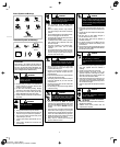
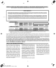
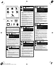
The safety alert symbol is used to identify safety
information about hazards that can result in personĆ
al injury.
A signal word (DANGER, WARNING, or CAUTION) is used
with the alert symbol to indicate the likelihood and the potential
severity of injury. In addition, a hazard symbol may be used to
represent the type of hazard.
DANGER indicates a hazard which, if not avoided,
will result in death or serious injury.
WARNING indicates a hazard which, if not avoided,
could result in death or serious injury.
CAUTION indicates a hazard which, if not avoided,
might result in minor or moderate injury.
CAUTION, when used without the alert symbol,
indicates a situation that could result in damage to
the outboard.