


39
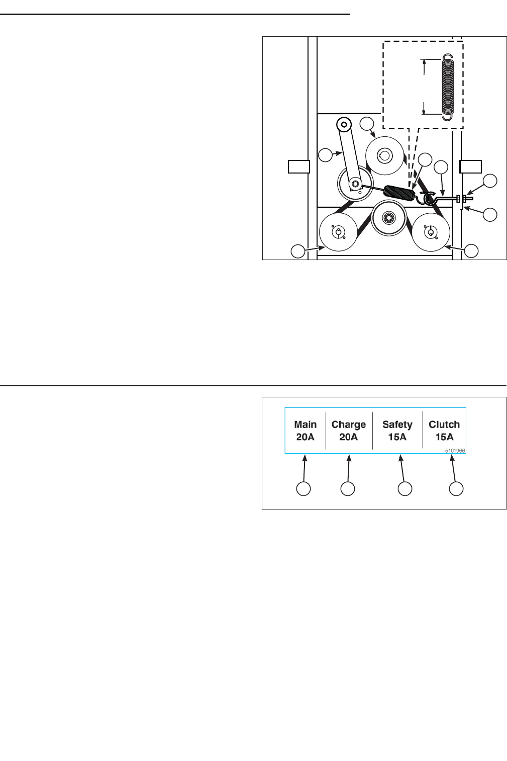
7”
(17,8 cm)
A
E
B
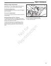
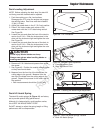
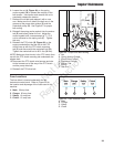
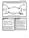
Figure 49. Pump Drive Belt Routing
A. Nut
B. Spring Anchor Eyebolt
C. Pump Drive Pulleys
D. Crankshaft Pulleys
E. Anchor Tab
F. Spring
G. Idler Arm
C
D
G
C
F
Regular Maintenance
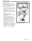
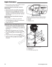
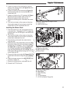
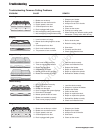
Fuse Locations
The fuse block is located underneath the left
instrument control panel. Refer to Figure 50 for
the location and amperage of the fuses used in this
machine.
A. Main: 20 amp fuse
B. Charge: 20 amp fuse
C. Safety: 15 amp fuse
D. Clutch: 15 amp fuse
A B C D
Figure 50. Fuse Location Decal
A. Main
B. Charge
C. Safety
D. Clutch
6. Loosen the nut (A, Figure 49) on the spring
anchor eyebolt (B) to release the majority of the
belt tension. Use caution and remove the nut to
completely release the tension.
7. Remove the old belt and replace it with a new
one. Make sure the V-side of the belt runs in the
grooves of the pump drive pulleys (C) and the
crankshaft pulley (D). See Figure 47 for proper
belt routing.
8. Reinstall the spring anchor eyebolt into the anchor
tab (E) and loosely fasten the nut. Adjust the
anchor eyebolt until a measurement of 7” (17,8
cm) is achieved on the spring coils (F). Tighten
the nuts.
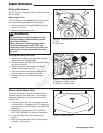
9. Reinstall the PTO clutch (B, Figure 48) on the
engine crankshaft so that the slot in the PTO
clutch lines up with the PTO clutch mounting
tab (C) and secure with the crankshaft bolt (A).
Tighten the crankshaft bolt to 65 ft. lbs (88 Nm).
NOTE: Make sure that the slot in the PTO clutch lines
up with the PTO clutch mounting tab underneath the
engine deck.
10. Reconnect the PTO clutch wire harness and wire
tie the harness out of the way of the PTO clutch
and the pump drive belt.
11. Reinstall the PTO drive belt.
Not for
Reproduction