


30
www.snapperpro.com
Regular Maintenance
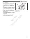
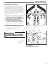
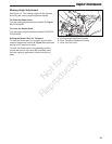
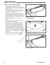
Figure 31. Adjusting the Range Selector Plate
A. Range Selector Hardware
B. Range Selector Pivot Hardware
C. Range Selector Plate
D. Brake Hub
1
4
3
2
A
C
B
D
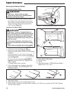
Parking Brake Adjustment
The parking brake system consists of two range
selector plates and two parking brake springs which
are located by the rear wheels of the unit. If the
parking brake needs to be adjusted the range selector
plates must be adjusted first, and then the length of
the parking brake springs must be set.
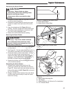
Adjusting the Range Selector Plate
1. Disengage the PTO, engage the parking brake,
stop the engine and remove the ignition key.
2. Chock the front tires to prevent the machine from
moving. Jack up the rear of the machine and
secure with jackstands.
3. Remove both of the rear wheels.
4. Disengage the parking brake.
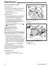
5. Remove the range selector hardware (A, Figure
31).
6. Loosen the range selector pivot hardware (B) just
enough so that you can pivot the range selector
plate (C).
7. Pivot the range selector plate towards the front
of the machine as far as you can and insert the
range selector hardware in the nearest hole.
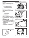
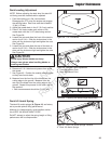
8. With the parking brake disengaged, attempt to pull
the brake hub (D) off of the unit.
• If their is resistance when you remove the brake
hub from the unit, continue with step # 9.
• If their is no resistance when you remove the
brake hub off the unit, place the brake hub back
on the unit and skip to step # 11.
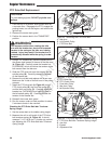
9. Remove the range selector hardware and pivot the
range selector plate until you can insert the range
selector hardware in the next lowest numbered
hole.
10. Re-check the hub for resistance by pulling the
brake up on and off the unit again. If their is
resistance move the range selector hardware in
the next lowest number hole until you can pull the
brake hub on and off without resistance. Place the
hub back on the unit.
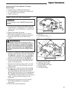
11. Tighten the range selector hardware (A) and the
range selector pivot hardware (B),
12. Reinstall the rear wheel.
13. Repeat the process for the other side of the unit.
14. Remove the jack and jack stands from underneath
the machine
Not for
Reproduction