


37
Regular Maintenance
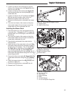
Mower Deck Drive Belt Replacement
1. Park the unit on a smooth, level surface such as
a concrete floor. Disengage the PTO, engage the
parking brake, turn off the engine, and remove the
ignition key.
2. Remove the mower deck guard.
3. Remove the PTO drive belt (see PTO DRIVE
BELT REPLACEMENT for removal instructions).
4. Lower the mower deck to its lowest cutting
position.
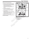
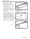
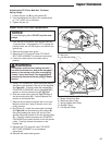
5. Using a 1/2” breaker bar, place the square end in
the square hole located in the end of the idler arm
(A, Figure 45). Carefully rotate the breaker bar
COUNTER-CLOCKWISE, which will relieve the
tension on the belt exerted from the idler arm.
6. Slide the mower deck drive belt over the edge of
the left spindle pulley (B). Carefully release the
tension on the breaker bar.
7. Remove the old belt and replace with a new one.
Make sure that the V-side of the belt runs in the
pulley grooves.
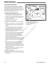
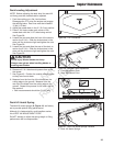
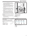
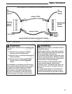
8. See Figure 46. Install the mower deck drive belt
(A, Figure 46) on the stationary idler pulleys (B),
the spring-loaded idler pulley (C) and all of the
spindle pulleys (D) except for the left spindle pulley
(E). Carefully rotate the breaker bar COUNTER-
CLOCKWISE and install the belt on the left spindle
pulley. Carefully release the tension on the
breaker bar.
9. Reinstall the PTO drive belt (see PTO DRIVE
BELT REPLACEMENT for re-installation
instructions).
10. Reinstall the mower deck guards.
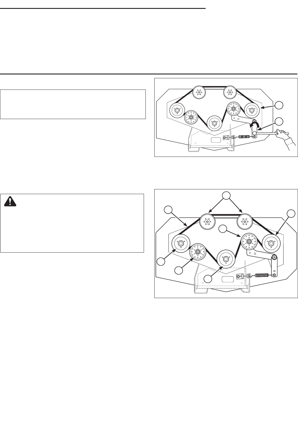
Figure 45. Mower Deck Belt Removal
A. Idler Arm
B. Left Spindle Pulley
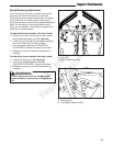
Figure 46. Mower Deck Belt Routing
A. Mower Deck Drive Belt
B. Stationary Idler Pulley
C. Spring-loaded Idler Pulley
D. Spindle Pulleys
E. Left Spindle Pulley
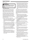
WARNING
Use extreme caution when rotating the idler
arm with the breaker bar, due to the increased
tension in the spring as the idler arm is being
rotated. Injury may result if the breaker bar is
prematurely released while the spring is under
tension.
A
B
B
C
D
B
D
E
A
NOTICE
To avoid damaging belts, DO NOT pry belts over
pulleys.
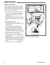
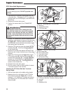
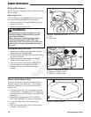
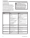
Adjusting the PTO Drive Belt Idler Tensioner
Spring Length
1. Loosen the jam nut (B) on the eyebolt (C).
2. Turn the adjustment nut (D) until a measurement
of 7-1/4” (18.42 cm) is achieved.
3. Tighten the jam nut.
Not for
Reproduction