


40
www.simplicitymfg.com | www.snapper.com
Troubleshooting, Adjustments, & Service
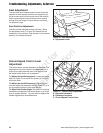
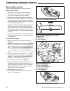
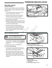
Figure 46. Mower Belt Routing
A. Arbor Pulleys
B. Back-Side Idler Pulleys
C. PTO Pulley
A
A
A
C
B
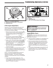
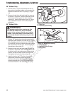
Figure 45. Release Belt Tension
A. Idler Arm
B. Stationary Idler Pulley
B
A
46” Models Only:
1. Pull the lever (A, Figure 43) towards the rear of
the machine to release tension on the mower belt.
Remove the belt from the PTO pulley (C, Figure
44).
2. Remove the old drive belt and install the new one
as shown in Figure 44. Note that the back on the
drive belt must ride against the back-side idler
pulleys (B). Use the belt tension lever (A, Figure
44) to release the tension on the idler pulley for
installation.
54” Models Only:
1. Using a 1/2” breaker bar, place the square end in
the square hole located in the idler arm (A, Figure
45). Carefully rotate the breaker bar COUNTER-
CLOCKWISE, which will relieve the tension on the
belt exerted from the idler arm. Slide the belt off
the stationary idler pulley (B).
2. Remove the old drive belt and install the new one
as shown in Figure 46. Make sure that the V-side
of the belt runs in the pulley groves of the spindle
pulleys, and that the back of the drive belt must
ride against the back-side idler pulleys (B).
3. Install the belt on the PTO pulley, the spindle
pulleys and all the idler pulleys except the
stationary idler pulley (B, Figure 46). Carefully
rotate the breaker bar COUNTER-CLOCKWISE
and install the belt on the stationary idler pulley.
WARNING
Use extreme caution when rotating the idler
arm with the breaker bar, due to increased
tension in the spring as the idler arm is being
rotated. Injury may result if the breaker bar is
prematurely released while the spring is under
tension.
Not for
Reproduction