


38
www.simplicitymfg.com | www.snapper.com
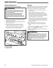
Mower Deck Leveling
Perform these adjustments on a flat level surface.
Side-To-Side Leveling
1. With the mower installed, place the rider on a
smooth, level surface such as a concrete floor.
Turn the front wheels so they are straight.
2. Check for bent blades and replace if necessary.
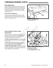
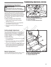
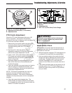
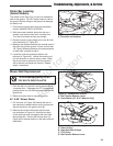
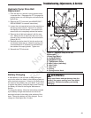
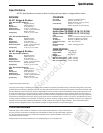
3. Place the mower cutting height pin in the 4th hole
from the bottom (see insert, Figure 40). Arrange
the outside mower blades so that they are pointing
from side-to-side (Figure 38).
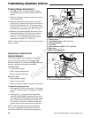
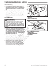
4. Measure the distance between the outside tips of
each blade and the ground (Figures 38 & 39). If
there is more than 1/8” (3mm) difference between
the measurements on each side, proceed to step
5. If the difference is 1/8” (3mm) or less, proceed
to step 6.
5. Use the rear leveling links (B, Figure 40) to adjust
the side-to-side leveling of the deck. Repeat step
4 if necessary.
Front-To-Back Leveling
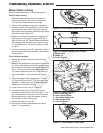
6. Arrange the blades so they face front-to-back
(Figure 41).
7. Measure the distance from the ground to the front
tip of the center blade, and from the ground to rear
tips of left-hand and right-hand blades (Figures 39
& 41). The front tip of the center blade should be
1/4” (6mm) higher than rear tips of left-hand and
right-hand blades. If not, proceed with steps 8 -
11.
8. Check the length of the hanging rods. The rear
(D, Figure 40) should be 15” (38,1cm) and is not
adjusted. To adjust the pitch of the mower deck,
adjust the front leveling nuts only.
9. Loosen the front lock nuts (E, Figure 40).
10. Turn the leveling nuts (A, Figure 40) counter-
clockwise to lower the front of mower deck. Turn
the nuts clockwise to raise the front of the mower.
Make adjustments in small increments, trying to
keep tension on both leveling nuts.
11. Tighten the front lock nuts (E).
12. Re-check the blade measurement then repeat
steps 7-11 as necessary.
Figure 41. Orient Blades Front-to-Back
Figure 38. Orient Blades Side-to-Side
Figure 39. Measure Blade Tips to Ground
A. Mower Deck
B. Blade Tip
C. Level Ground
A
B
C
Figure 40. Mower Leveling
A. Front Leveling Nuts
B. Rear Leveling Rods
C. 4th Cutting Height Hole
D. Rear Hanger Rods
E. Front Lock Nuts
B
D
C
A
E
Troubleshooting, Adjustments, & Service
Not for
Reproduction