


5
Always use original equipment manufacturer 0.080 in. (2.03 mm)
replacement line. Line other than the specified may make the
engine overheat or fail.
There are two methods to replace the trimming line:
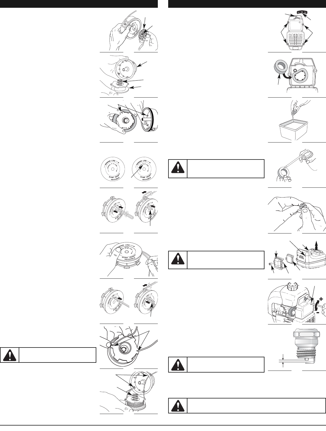
• Wind the inner reel with new line
• Install a prewound inner reel
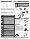
Winding the Existing Inner Reel
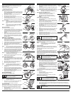
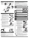
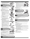
1. Hold the outer spool with one hand and unscrew the Bump
Knob™ counterclockwise (Fig. 12). Inspect the bolt inside
the Bump Knob to make sure it moves freely. Replace the
Bump Knob if damaged.
2. Remove the inner reel from the outer spool (Fig. 13).
3. R
emove spring from the inner reel (Fig. 13).
4. Use a clean cloth to clean the the inner reel, spring, shaft,
and inner surface of the outer spool.
5. Check the indexing teeth on the inner reel and outer spool
for wear (Fig. 14). If necessary, remove burrs or replace the
reel and spool.
NOTE: SplitLine™ can only be used with the inner reel with the
slotted holes. Single line can be used on either type of
inner reel. Use Figure 15 to identify the inner reel you
have.
NOTE: Always use the correct line length when installing
trimming line on the unit. The line may not release
properly if the line is too long.
Single Line Installation
Go To Step 8 for SplitLine™ Installation
6. Take approximately 20 feet (6 m) of new trimming line, loop
it into two equal lengths. Insert each end of the line through
one of the two holes in the inner reel (Fig. 16). Pull the line
through the inner reel so that the loop is as small as
possible.
7. Wind the lines in tight even layers, onto the reel (Fig. 17).
Wind the line in the direction indicated on the inner reel.
Place your index finger between the two lines to stop the
lines from overlapping. Do not overlap the ends of the line.
Proceed to step 11.
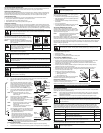
SplitLine™ Installation
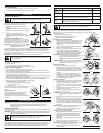
8. Take approximately 10 feet (3 m) of new trimming line.
Insert one end of the line through one of the two holes in
the inner reel (Fig. 18). Pull the line through the inner reel
until only about 4 inches is left out.
9.
Insert the end of the line into the open hole in the inner reel and
pull the line tight to make the loop as small as possible (Fig. 18).
10. Before winding, split the line back about 6 inches.
11. Wind the line in tight even layers in the direction indicated on
the inner reel.
NOTE: Failure to wind the line in the direction indicated will
cause the cutting attachment to operate incorrectly.
12.
Insert the ends of the line into the two holding slots (Fig. 19).
13.
Insert the ends of the line through the eyelets in the outer spool
and place inner reel with spring inside the outer spool (Fig. 20).
Push the inner reel and outer spool together. While holding the
inner reel and outer spool, grasp the ends and pull firmly to
release the line from the holding slots in the reel.
NOTE: The spring must be assembled on the inner reel before
reassembling the cutting attachment.
14. Hold the inner reel in place and install the bump knob by
turning clockwise. Tighten securely.
INSTALLING A PREWOUND REEL
1. Hold the outer spool with one hand and unscrew the bump
knob counterclockwise (Fig. 12). Inspect the bolt inside the
bump knob to make sure it moves freely. Replace the bump
knob if damaged.
2. Remove the old inner reel from the outer spool (Fig. 13).
3. Remove the spring from the old inner reel (Fig. 13).
4. Place the spring in the new inner reel.
NOTE: The spring must be assembled on the inner reel
before reassembling the cutting attachment.
5. Insert the ends of the line through the eyelets in the outer
spool (Fig. 20).
6. Place the new inner reel inside the outer spool. Push the
inner reel and outer spool together. While holding the inner
reel and outer spool, grasp the ends and pull firmly to release
the line from the holding slots in the spool.
7. Hold the inner reel in place and install the bump knob by
turning clockwise. Tighten securely.
AIR FILTER MAINTENANCE
Removing the Air Filter/Muffler Cover
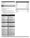
1. Place the blue choke lever in Position 2 (Fig. 21).
NOTE: The blue choke lever must be in Position 2 to remove
the air filter/ muffler cover.
2. Remove the four (4) screws securing the air filter/muffler
cover (Fig. 21). Use a T-20 Torx bit screwdriver.
3. Pull the cover from the engine. Do not force.
Cleaning the Air Filter
Clean and re-oil the air filter every 10 hours of operation. It is an important
item to maintain. Failure to maintain your air filter properly can result in
poor performance or can cause permanent damage to your engine.
1. Remove air filter/muffler cover. Refer to Removing the Air
Filter/Muffler Cover.
2. Turn cover over and look inside to locate the air filter. Remove the air filter from inside the air
filter/muffler cover (Fig. 22).
MAINTENANCE AND REPAIR INSTRUCTIONS MAINTENANCE AND REPAIR INSTRUCTIONS
3. Wash the filter in detergent and water (Fig. 23). Rinse the
filter thoroughly. Squeeze out excess water. Allow it to dry
completely.
4. Apply enough clean SAE 30 oil to lightly coat the filter (Fig. 24).
5. Squeeze the filter to spread and remove excess oil (Fig. 25).
6. Replace the air filter inside the air filter/muffler cover (Fig. 22).
NOTE: Operating the unit without the air filter and air
filter/muffler cover assembly will VOID the warranty.
Reinstalling the Air Filter/Muffler Cover
1. Place the air filter/muffler cover over the back of the
carburetor and muffler. Align the screw holes.
2. Insert the four (4) screws into the holes in the air
filter/muffler cover (Fig. 21) and tighten. Do not over
tighten.
SPARK ARRESTOR MAINTENANCE
1. Remove air filter/muffler cover. Refer to Removing the Air
Filter/Muffler Cover.
2. Locate the muffler, but do not remove it. Find the screw on
the bottom of the muffler (Fig. 26). Remove the screw using
either a torx #20 or flat blade screwdriver.
3. Carefully pry up the left side spark arrestor hood. Two tabs
act as hinges on the right side of the hood. Flip open the
spark arrestor hood like a door and then pull its tabs out of
the muffler slots.
4. Using a small flat blade screwdriver, carefully pry the spark
arrestor screen out from the inside of the spark arrestor
hood.
5. C
lean the spark arrestor screen with a wire brush. Replace it if it
is damaged, or if you are unable to clean it thoroughly.
6.
Reinstall the spark arrestor screen snugly back into the spark
arrestor hood.
7. Reinstall the two hood tabs into the two muffler slots and
flip the spark arrestor hood closed.
8.
Replace the screw you removed in Step 2 and tighten it securely.
9. Reinstall the air filter/muffler cover.
CARBURETOR ADJUSTMENT
The idle speed of the engine is adjustable through the air
filter/muffler cover (Fig. 27).
NOTE: Careless adjustments can seriously damage your
unit. An authorized service dealer should make
carburetor adjustments.
Check Fuel Mixture
Old and/or improperly mixed fuel is usually the reason for improper unit
performance. Drain and refill the tank with fresh, properly-mixed fuel prior
to making any adjustments. Refer to Oil and Fuel Information.
Clean Air Filter
The condition of the air filter is important to the operation of the unit. A dirty
air filter will restrict air flow and change the air/fuel mixture. This is often
mistaken for an out of adjustment carburetor. Check the condition of the air
filter before adjusting the idle speed screw. Refer to Air Filter Maintenance.
Adjust Idle Speed Screw
If, after checking the fuel mixture and cleaning the air filter, the
engine still will not idle, adjust the idle speed screw as follows:
1. Start the engine and let it run at a high idle for a minute to
warm up. Refer to Starting/Stopping Instructions.
2. Release the throttle trigger and let the engine idle. If the engine
stops, insert a small phillips screwdriver into the hole in the air
filter/muffler cover (Fig. 27). Turn the idle speed screw in,
clockwise, 1/8 of a turn at a time (as needed) until the engine
idles smoothly.
3. If the engine appears to be idling too fast, turn the idle speed
screw counterclockwise 1/8 of a turn at a time (as needed),
to reduce idle speed.
Checking the fuel mixture, cleaning the air filter, and adjusting the
idle speed should solve most engine problems. If not and all of the
following are true:
•
the engine will not idle
• the engine hesitates or stalls on acceleration
• there is a loss of engine power
Have the carburetor adjusted by an authorized service dealer.
REPLACING THE SPARK PLUG
Use a Champion RDJ7Y spark plug, or equivalent. The correct air gap is 0.025 inch (0.635 mm). Remove the
plug after every 25 hours of operation and check its condition.
1. Stop the engine and allow it to cool. Grasp the plug wire firmly and pull it from the spark plug.
2. Clean around the spark plug. Remove the spark plug from the cylinder head by turning a 5/8-inch
socket counterclockwise.
Bolt
Bump Knob™
Fig. 12
Outer Spool
Spring
Inner Reel
Fig. 13
For Use with
Single Line ONLY
Slotted
Holes
Fig. 15
Indexing Teeth
Fig. 14
Loop
Fig. 16
Fig. 17
Loop
Fig. 18
Index Teeth
Fig. 19
Spring
Fig. 20
Blue Choke
Lever
Screws
Position 2
Fig. 21
Air Filter
Inside Muffler Cover
Fig. 22
Fig. 23
Fig. 24
Fig. 25
WARNING:
If the spark arrestor hood and
spark arrestor screen are not tightened securely,
they could fall off causing damage to the unit
and possible serious personal injury.
WARNING:
The cutting attachment will spin
during idle speed adjustments. Wear protective
clothing and observe all safety instructions to
prevent serious personal injury.
Slots
Spark
Arrestor
Hood
Screw
Fig. 26
WARNING:
To prevent serious personal injury,
make sure the cutting attachment has stopped rotating
after you turn it off and before you set it down.
For Use with
Splitline™ or
Single Line ONLY
WARNING:
To avoid serious personal injury,
always turn your unit off and allow it to cool
before you clean or service it.
Screws
Tabs
Spark Arrestor
Screen
Engine
Muffler
Idle Speed Screw
Fig. 27
0.025 in.
(0.635 mm)
Fig. 28
WARNING:
Do not sand blast, scrape or clean electrodes. Grit in the engine could
damage the cylinder.
Eyelets