


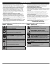


OIL AND FUEL INFORMATION
OIL AND FUEL MIXING INSTRUCTIONS
Old and/or improperly mixed fuel are the main reasons for the unit not running properly. Be sure to use
fresh, clean unleaded fuel. Follow the instructions carefully for the proper fuel/oil mixture.
DEFINITION OF BLENDED FUELS
Today's fuels are often a blend of gasoline and oxygenates such as ethanol, methanol, or MTBE (ether).
Alcohol-blended fuel absorbs water. As little as 1% water in the fuel can make fuel and oil separate. It
forms acids when stored. When using alcohol-blended fuel, use fresh fuel (less than 60 days old).
USING BLENDED FUELS
If you choose to use a blended fuel, or its use is unavoidable, follow recommended precautions:
• Always use the fresh fuel mix explained in your operator's manual
• Always agitate the fuel mix before fueling the unit
• Drain the tank and run the engine dry before storing the unit
USING FUEL ADDITIVES
The bottle of 2-cycle oil that came with your unit contains a fuel additive which will help inhibit corrosion
and minimize the formation of gum deposits. It is recommended that you use our 2-cycle oil with this unit.
If unavailable, use a good 2-cycle oil designed for air-cooled engines along with a fuel additive, such as
STA-BIL® Gas Stabilizer or an equivalent. Add 0.8 oz. (23 ml.) of fuel additive per gallon of fuel according
to the instructions on the container. NEVER add fuel additives directly to the unit's fuel tank.
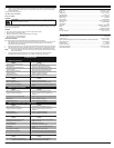
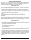
Thoroughly mix the proper ratio of 2-cycle engine oil with
unleaded gasoline in a separate fuel can. Use a 40:1 fuel/oil
ratio. Do not mix them directly in the engine fuel tank. See the
table below for specific gas and oil mixing ratios.
NOTE: One gallon (3.8 liters) of unleaded gasoline mixed
with one 3.2 oz. (95 ml.) bottle of 2-cycle oil makes
a 40:1 fuel/oil ratio.
NOTE: Dispose of the old fuel/oil mix in accordance to
Federal, State and Local regulations.
MIXING RATIO - 40:1
UNLEADED GAS 2 CYCLE OIL
1 GALLON US
(3.8 LITERS)
3.2 FL. OZ.
(95 ml)
1 LITER 25 ml
STARTING/STOPPING INSTRUCTIONS
STARTING INSTRUCTIONS
1. Mix gas with oil. Fill fuel tank with fuel/oil mixture. See Oil and Fuel Mixing Instructions.
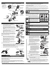
2.
Make sure the On/Off Stop Control in the ON ( I ) position
(Fig. 6).
3. Fully press and release the primer bulb 10 times,
slowly. Some amount of fuel should be visible in the
primer bulb and fuel lines (Fig. 7). If you can’t see
fuel in the bulb, press and release the bulb as many
times as it takes before you can see fuel in it.
4. Place the blue choke lever in Position 1 (Fig. 7).
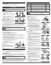
5. Crouch in the starting position (Fig. 8) and squeeze
the throttle control. Pull the starter rope briskly 5
times.
NOTE: The unit uses EZ-Pull Version 3™, which
significantly reduces the effort required to
start the engine.
6. Place the blue choke lever in Position 2.
7. While squeezing the throttle control, pull the starter
rope briskly until the engine starts.
8. Keep the throttle squeezed and allow the engine to
warm up for 15 to 30 seconds.
NOTE: Engine may take longer to warm up and reach
maximum operating speed at colder
temperatures.
NOTE: Unit is properly warmed up when engine
accelerates without hesitation.
9. Once the engine is warmed up, place the blue choke
lever in Position 3 (Fig. 7). The unit is ready for use.
IF...
The engine hesitates, return choke lever to Position 2
(Fig. 7) and continue warm up.
IF...
The engine does not start, go back to step 3.
IF...
The engine fails to start after a few attempts, place the
blue choke lever in Position 3 and squeeze the throttle
control. Pull the starter rope briskly 3 to 8 times. The
engine should start. If not, repeat.
IF WARM... If the engine is already warm, make sure the
On/Off Stop control is in the ON position and start the unit with the blue choke lever in Position
2. After the unit starts, move the blue choke lever to Position 3.
STOPPING INSTRUCTIONS
1. Release your hand from the throttle control. Allow the engine to cool down by idling.
2.
Press and hold On/Off Stop Control in the OFF (O) position until engine comes to a complete stop.
OPERATING INSTRUCTIONS
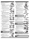
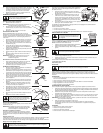
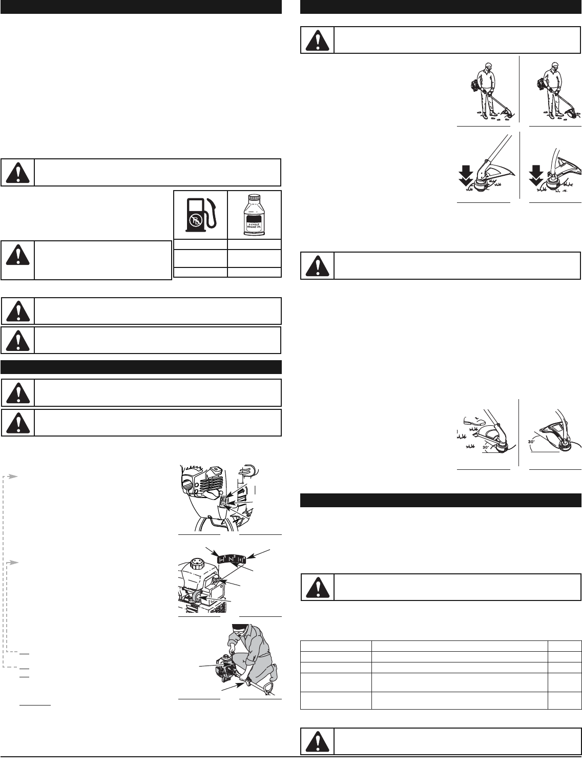
HOLDING THE TRIMMER
Before operating the unit, stand in the operating position
(Fig. 9). Check for the following:
•
The operator is wearing eye protection and proper clothing
• With a slightly-bent right arm, the operator’s right hand is
holding the shaft grip
• The operator’s left arm is straight, the left hand holding
the D-handle
• The unit is at waist level
•
The cutting attachment is parallel to the ground and easily
contacts the grass without the need to bend over
ADJUSTING TRIMMING LINE LENGTH
The Bump Head™ cutting attachment allows you to release
trimming line without stopping the engine. To release more line,
lightly tap the cutting attachment on the ground (Fig. 10) while
operating the trimmer at high speed.
NOTE: Always keep the trimming line fully extended.
Line release becomes more difficult as
cutting line becomes shorter
Each time the head is bumped, about 1 inch (25.4 mm) of
trimming line releases. A blade in the cutting attachment
shield will cut the line to the proper length if any excess line is released.
For best results, tap the bump knob on bare ground or hard soil. If you attempt a line release in tall grass,
the engine may stall. Always keep the trimming line fully extended. Line release becomes more difficult
when the cutting line gets shorter.
NOTE: Do not rest the Bump Head™ on the ground while the unit is running.
Some line breakage will occur from:
• Entanglement with foreign matter
• Normal line fatigue
• Attempting to cut thick, stalky weeds
• Forcing the line into objects such as walls or fence posts
TIPS FOR BEST TRIMMING RESULTS
• Keep the cutting attachment parallel to the ground.
• Do not force the cutting attachment. Allow the tip of the line to do the cutting, especially along walls.
Cutting with more than the tip will reduce cutting efficiency and may overload the engine.
• Cut grass over 8 inches (200 mm) by working from top to bottom in small increments to avoid
premature line wear or engine drag.
• Cut from right to left whenever possible. Cutting to the left improves the unit's cutting efficiency.
Clippings are thrown away from the operator.
• Slowly move the trimmer into and out of the cutting area at the desired height. Move either in a
forward-backward or side-to-side motion. Cutting shorter lengths produces the best results.
• Trim only when grass and weeds are dry.
• The life of your cutting line is dependent upon;
• Adherence of the listed trimming techniques
• What vegetation is cut
• Where vegetation is cut
For example, the line will wear faster when trimming against a
foundation wall as opposed to trimming around a tree.
DECORATIVE TRIMMING
Decorative trimming is accomplished by removing all
vegetation around trees, posts, fences, etc.
Rotate the whole unit so that the cutting attachment is at a 30° angle to the ground (Fig. 11).
4
CAUTION:
For proper engine operation and maximum reliability, pay strict attention to
the oil and fuel mixing instructions on the 2-cycle oil container. Using improperly mixed fuel
can severely damage the engine.
WARNING:
Gasoline is extremely flammable.
Ignited vapors may explode. Always stop the engine
and allow it to cool before filling the fuel tank. Do not
smoke while filling the tank. Keep sparks and open
flames at a distance from the area.
WARNING:
Remove fuel cap slowly to avoid injury from fuel spray. Never operate the
unit without the fuel cap securely in place.
WARNING:
Add fuel in a clean, well ventilated outdoor area. Wipe up any spilled fuel
immediately. Avoid creating a source of ignition for spilt fuel. Do not start the engine until
fuel vapors dissipate.
WARNING:
Remove fuel cap slowly to avoid injury from fuel spray. Never operate the
unit without the fuel cap securely in place.
WARNING:
Avoid accidental starting. Make sure you are in the starting position when
pulling the starter rope (Fig. 8). To avoid serious injury, the operator and unit must be
in a stable position while starting.
Stop/Off (O)
On/Off Stop
Control
Start/On (I)
Fig. 6
Position 1
Position 3
Position 2
Blue Choke
Lever
Fig. 7
Starting Position
Starter
Rope
Throttle Control
Fig. 8
WARNING:
Always wear eye, hearing, foot and body protection to reduce the risk of
injury when operating this unit.
CAUTION:
Do not remove or alter the line cutting blade assembly. Excessive line length
will make the unit overheat. This may lead to serious personal injury or damage to the unit.
MAINTENANCE AND REPAIR INSTRUCTIONS
Primer Bulb
BL100
BL150
Fig. 11
BL100
BL150
Fig. 9
BL100
BL150
Fig. 10
MAINTENANCE SCHEDULE
Perform these required maintenance procedures at the frequency stated in the table. These procedures
should also be a part of any seasonal tune-up.
NOTE: Some maintenance procedures may require special tools or skills. If you are unsure about
these procedures take your unit to any non-road engine repair establishment, individual or
authorized service dealer.
NOTE: Maintenance, replacement, or repair of the emission control devices and system may be
performed by any non-road engine repair establishment, individual or authorized service dealer.
In order to assure peak performance of your engine, inspection of the engine exhaust port may be necessary
after 50 hours of operation. If you notice lost RPM, poor performance or general lack of acceleration, this
service may be required. If you feel your engine is in need of this inspection, refer service to any non-road
engine repair establishment, individual or authorized service dealer for repair. DO NOT attempt to perform this
process yourself as engine damage may result from contaminants involved in the cleaning process for the port.
WARNING:
To prevent serious injury, never perform maintenance or repairs with unit
running. Always service and repair a cool unit. Disconnect the spark plug wire to ensure that
the unit cannot start.
FREQUENCY MAINTENANCE REQUIRED SEE
Before starting engine Fill fuel tank with fresh fuel p. 4
Every 10 hours Clean and re-oil air filter p. 7
Every 25 hours Check and clean spark arrestor
Check spark plug condition and gap
p. 8
p. 8
Every 50 hours Inspect exhaust port and spark arrestor screen for clogging or
obstruction to assure maximum performance levels.
p. 8
LINE INSTALLATION
This section covers both SplitLine™ and standard single line installation.
WARNING:
N
ever use metal-reinforced line, wire, chain or rope. These can break off and
become dangerous projectiles.