


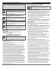
RULES FOR SAFE OPERATION
This operator's manual describes safety and international symbols
and pictographs that may appear on this product. Read the
operator's manual for complete safety, assembly, operating and
maintenance and repair information.
• SAFETY ALERT SYMBOL
Indicates danger, warning or caution. May be used in
conjunction with other symbols or pictographs.
• HOT SURFACE WARNING
Do not touch a hot muffler or cylinder. You may get
burned. These parts get extremely hot from operation.
When turned off they remain hot for a short time.
• WARNING - READ OPERATOR'S MANUAL
Read the operator’s manual(s) and follow all warnings and
safety instructions. Failure to do so can result in serious
injury to the operator and/or bystanders.
• WEAR EYE AND HEARING PROTECTION
WARNING: Thrown objects and loud noise can cause
severe eye injury and hearing loss. Wear eye protection
meeting ANSI Z87.1-1989 standards and ear protection when
operating this unit. Use a full face shield when needed.
• KEEP BYSTANDERS AWAY
WARNING: Keep all bystanders, especially children
and pets, at least 50 feet (15 m.) from the operating area.
• THROWN OBJECTS AND ROTATING CUTTER CAN
CAUSE SEVERE INJURY
WARNING: Small objects can be propelled at high
speed, causing injury. Keep away from the rotating rotor.
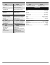
SYMBOL MEANING
SYMBOL MEANING
• CHOKE CONTROL
1. • FULL choke position
2. • PARTIAL choke position
3. • RUN choke position
• UNLEADED FUEL
Always use clean, fresh unleaded fuel
• OIL
Refer to operator’s manual for the proper type of oil.
• ON/OFF STOP CONTROL
ON / START / RUN
• ON/OFF STOP CONTROL
OFF or STOP
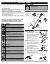
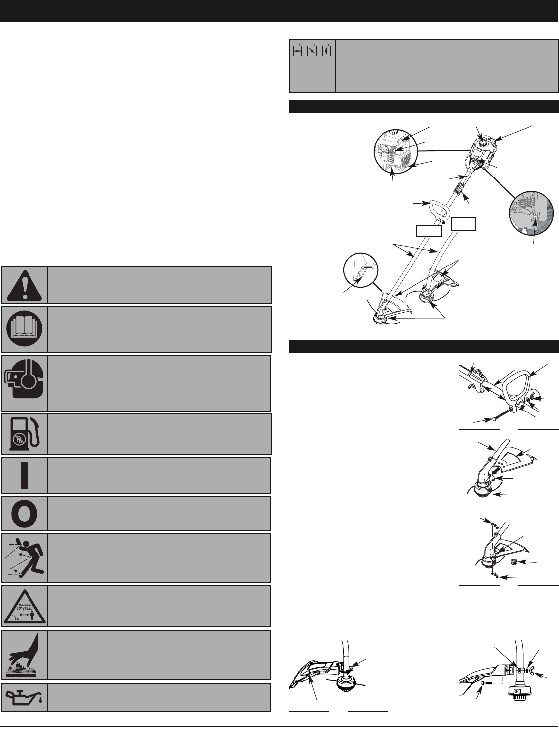
KNOW YOUR UNIT
APPLICATIONS
As a trimmer:
• Cutting grass and light
weeds
• Edging
• Decorative trimming around
trees, fences, etc.
Blue Choke Lever
Throttle
Control
D-Handle
Shaft Grip
Primer Bulb
Air Filter/Muffler Cover
Spark Plug
Shaft Housing
Starter Rope Grip
Line Cutting
Blade
Muffler
On/Off Stop
Control
Cutting Attachment
Cutting
Attachment
Shield
Fuel Cap
3
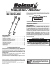
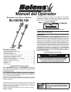
BL100
BL150
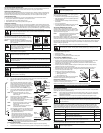
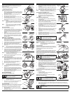
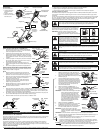
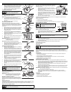
INSTALL AND ADJUST THE D-HANDLE
1. P
ush the D-handle down onto the shaft housing so that the
handle slants towards the shaft grip (Fig. 1). The squared bolt
hole in the handle is to the right.
2. Insert the shoulder bolt into the squared hole in the handle and
push through. On the left side of the handle, place the washer
on the bolt, then screw the wing nut onto the bolt. Do not
tighten until you make the handle adjustment.
3. R
otate the D-handle to place the grip above the top of the shaft
housing. Place it a minimum of 6 inches (15.24 cm) from the
end of the shaft grip.
4. While holding the unit in the operating position (Fig. 9),
position the D-handle to the location that provides you the
best grip.
5. Tighten the wing nut until the D-handle is secure.
INSTALLING THE CUTTING SHIELD
Use the following instructions if the cutting attachment shield on
your unit is not installed or if you ever need to re-install it.
IBL150
1. Slide the cutting attachment shield into the shield mount on
the cutting attachment. Align the screw holes in the shield
with the holes in the cutting attachment shield mount (Fig.
2).
2. Place one of the three (3) supplied hex lock nuts into one of
the three recessed holes on the top of the cutting
attachment shield (Fig 3).
3. I
nstall a screw into the hole from the bottom of the cutting
attachment shield. Screw it into the nut installed in step 2 until it
is started (Fig 3). Do not tighten.
4. R
epeat steps 2 and 3 until all three screws have been started.
Then tighten all screws securely with a Phillips head screwdriver.
BL100
1.
Place the cutting attachment shield onto the shaft housing. Be
sure the guard mounting bracket slides into the slot on the edge of the cutting shield. Rotate the shield into
place, counterclockwise (Fig. 4). The holes in the guard mounting bracket and cutting attachment shield will
line up.
2. From inside the cutting attachment shield, push the square bolt through the hole until the threaded end
protrudes through the guard mounting bracket (Fig. 5).
3. Put the washer on the bolt, then screw the wing nut onto the bolt and tighten.
ASSEMBLY INSTRUCTIONS
Shaft Grip
Shaft
Housing
D-Handle
Tighten
Wing
Nut
Bolt
Fig. 1
Washer
Minimum
6 inches
(15.24 cm)
Shaft Housing
Shield Mount
Cutting
Attachment
Shield
Cutting
Attachment
Fig. 2
Nuts (3)
Recessed Holes
Hex Lock
Nut
Screws (3)
Fig. 3
Guard
Mounting
Bracket
Cutting Attachment Shield
Fig. 4
Guard Mounting
Bracket
Washer
Wing Nut
Square Bolt
Fig. 5
• To reduce fire hazard, replace a faulty muffler and spark arrestor.
Keep the engine and muffler free from grass, leaves, excessive
grease or carbon build up.
OTHER SAFETY WARNINGS
• Never store a fueled unit inside a building where fumes may reach
an open flame or spark.
• Allow the engine to cool before storing or transporting. Be sure to
secure the unit while transporting.
• Store the unit in a dry area, locked up or up high to prevent
unauthorized use or damage, out of the reach of children.
• Never douse or squirt the unit with water or any other liquid. Keep
handles dry, clean and free from debris. Clean after each use, see
Cleaning and Storage instructions.
•
Keep these instructions. Refer to them often and use them to instruct other
users. If you loan someone this unit, also loan them these instructions.
SAVE THESE INSTRUCTIONS