


6
SECTION 6: SET-UP INSTRUCTIONS
This guide covers models 462B 5 H.P. thru 465A
8 H.P. chipper shredders. Much of this guide
pertains to both models. However, there are
some areas where only one model is covered.
Use only the information that is appropriate for
your model.
Start with Step 1 to set-up you new
chipper shredder.
All models.
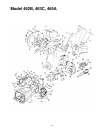
1. Pull the spark plug wire off of the spark plug.
See Figure 1
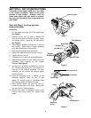
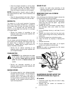
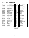
2. Remove six hex nuts (A) and six washers (B)
from the weld studs on the flail housing. Leave
the support plate in place on the weld studs.
See Figure 2
3. Place hopper assembly into position in front of
flail housing. Align holes in hopper assembly
collar with weld studs on flail housing.
4. Slide hopper assembly onto weld studs.
5. Replace the washers (B) and the hex nuts (A).
6. Tighten the hex nuts (A).
7. Lift hopper until it clicks into the raised position.
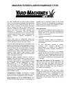
8. Remove wing knobs (C) from each side of the
discharge chute opening on the chipper
shredder.
See Figure 3
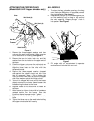
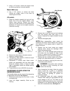
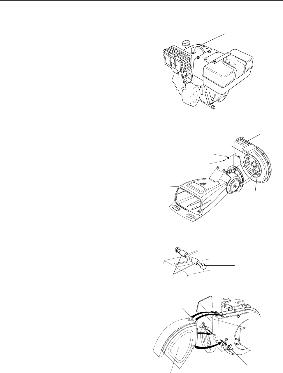
9. Use two 7/16" wrenches to remove hex lock nut
(D). Remove two spacers (E), and hex bolt (F)
from top of the housing assembly. For easy
assembly, do not remove the second spacer
from the hex bolt.
10. Place the discharge chute in position on the
discharge opening. Insert hex bolt (F) and
spacer (E) through hinge on discharge chute
and housing (spacer fits inside of hinge).
11. Place second spacer (E) over hex bolt (F)
inside the other half of the hinge. Secure with
hex lock nut (D). Tighten securely.
12. Secure both sides of discharge chute to flail
housing using wing knobs (C). Tighten wing
knobs.
Figure 1
Figure 2
Figure 3
Spark Plug Wire
Hex Nut (A)
Weld Stud
Hopper
Washer (B)
Support Plate
Flail Housing
Assembly
Hex Lock Nut (D)
Spacer (E)
Hex Bolt (F)
Chute
Discharge
Hinge
Wing Knob (C)