


Part No 830542 Form No F062007A
9
VQ Owner’s Manual
ASSEMBLY
1. UPPER HANDLE (item 41). Assemble securely to lower handle stubs (item 37) and handle brace (item 36), using screws
(item 120 & 121), so that screw heads are on inside of handle. Otherwise, premature bag wear could result.
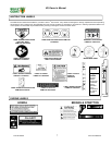
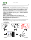
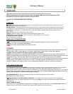
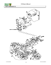
2. NOZZLE DOOR CONTROLS. Assemble ball joints (item 73), jam nuts (item 138), to both ends of rod (item 47). Do not fully
tighten jam nuts.
Using screw (item 113), washer (item 143) and lock nut (item 131), connect one end of rod (item 47) to nozzle door mounting.
(See Figure 5). Using rod, pull nozzle door open horizontal to ground and hold opposite end of rod next to mounting hole on
remote lever (item 48), already assembled onto upper handle. (See Figure 1). If necessary, adjust rod length using threads
provided on rod. Adjust rod length to give a minimum of 1.0" (25.4 mm) hand clearance between lever & maximum forward
throttle position when door is open. Assemble upper end of rod to lever on handle using same hardware item numbers as
shown above. (See figure 1& 2). Tighten jam nuts.
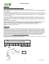
3. EXHAUST ASSY. Place flange gasket (item 35) onto housing of main unit and assemble exhaust elbow to housing using
screws (item 117), washers (item 140) and lock nuts (item 132), provided in parts bag. The rear hole mounts deflector (item
118), using screw assembly (already attached to deflector) and lock nut (item 132). Bend opposite end of deflector down until
notch in rear of deflector catches onto handle brace (item 36) (see figure 3).
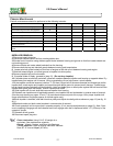
4. DEBRIS BAG (Item 50) (see figure 4).
4.1 Unfold and place mouth of bag over exhaust elbow, completely covering the discharge opening with bag neck straps,
placing one on each side of elbow flange.
COMPLETELY TIGHTEN BAG NECK STRAPS
4.2 Attach rear hanger straps of bag to the hanger loops located one on each side of the upper handle.
5. CABLES AND WIRES. Attach to the handle using cable clamps (item 44).
6. Secure engine starter rope into starter rope guide (Item 177) using hardware that is preassembled to the lower handle.
7. INSPECT ALL PARTS & MECHANICAL FASTENERS for security and integrity.
8. Note: See debris bag conditioning under operation section on page 11).
SELF PROPELLED ONLY (before starting unit).
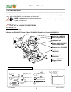
9. CONTROL ASSY (item 77).
Before starting engine, check for neutral by placing the control into neutral and engaging the bail, the unit has been
adjusted at the factory and should free wheel. If not, adjust as needed by placing the control (item 77) and
transmission offset link (item 68) into neutral and adjust nuts on control cable (item 75).
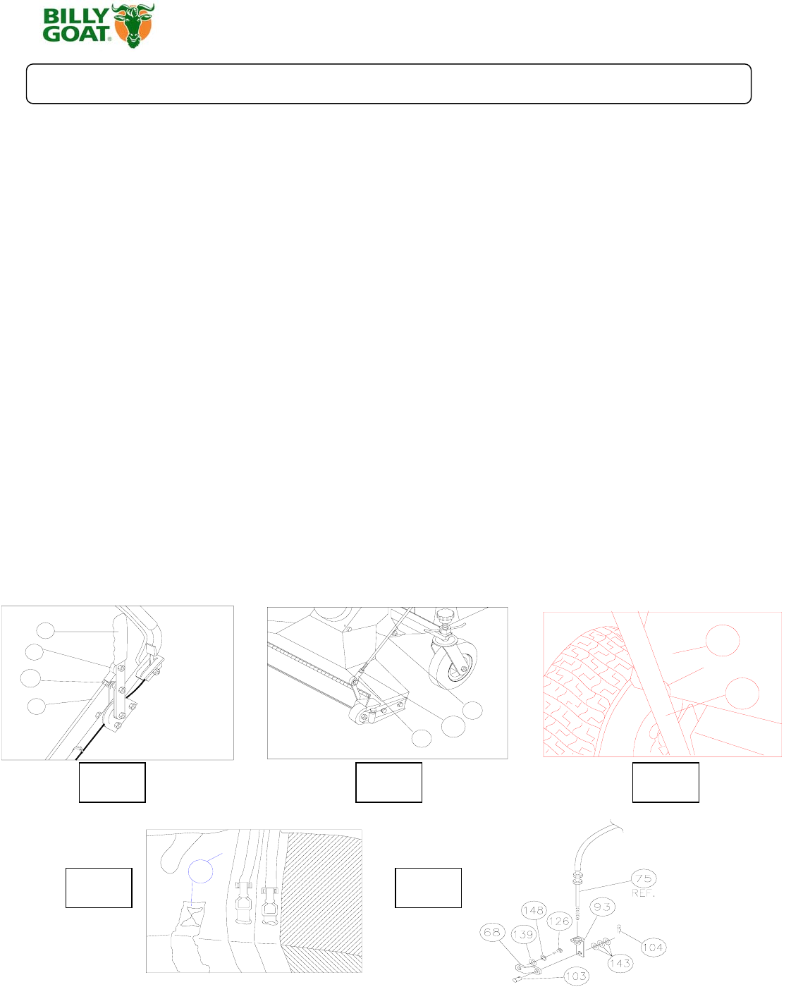
10. Check tire pressure and lubricate all grease and oil points
(see MAINTENANCE).
11. Connect spark plug wire.
48
73
138
47
Fig. 1
47
138
73
Fig. 2
118
36
Deflector notch
Fig. 3
50
Fig. 4 Fig. 5