


4-18 Operation
MN2417
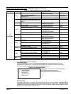
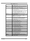
Table 4-9 Setpoints Continued
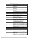
GCB CloseDelay
GCB can be closed earliest GCB CloseDelay after Stabil time when all
electric values are in overunder voltage and over−under frequency limits.
Step: 1 s; Range: 0 − 300 s
Stabil time Generator Nominal voltage is detected during genset start after starter is
switched off and Idle time elapses. Electric generator protections are
active since detection. Step: 1 s; Range: 0 − 300 s
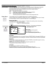
MinStpValvTime Binary output Stop solenoid closes when stop sequence begins and
closes at least for MinStpValvTime. Example MinStpValvTime = 20 sec.
a) When engine stops (RPM=0) in 10 seconds, Binary output Stop
solenoid still stays closed for 10 sec.
b) When engine stops in 30 seconds, Binary output Stop solenoid opens
10 seconds after RPM=0 and Vg =0 and Oil pressure = 0. Those 10 sec is
fix time for safe stop. Step: 1s; Range: 0 − 180 s
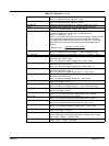
Note: Stop of engine is detected when all following conditions are met:
RPM =0, Oil pressure < StartingPOil and Generator voltage < 10 VAC.
Stop fail is detected when is difference between those conditions, e.g
RPM=O and Generator voltage > 10V.
Cooling time Runtime of the unloaded gen−set to cool the engine before stop.
Step: 1s; Range: 0 − 3600 s
D+ function ENABLED: The D+ terminal is used for both functions running
engine
detection and charge fail detection.
CHRGFAIL: The D+ terminal is used for charge fail detection only
DISABLED: The D+ terminal is not used.
Note: Magnetization current is independent of this setpoint value.
Eng prot del During the start of the gen−set, some engine protections have to be
blocked (e.g. Oil pressure). The protections are unblocked after the
Protection del time. The time starts after reaching Start RPM.
Step: 1s; Range: 0 − 300 s
Horn timeout Max time limit of horn sounding. Set to zero if you want to leave the output
HORN open. Step: 1s; Range: 0 − 600 s
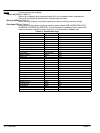
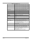
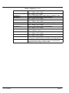
Overspeed Threshold for over speed protection.
Step: 1% of nominal RPM; Range: 100 − 150%
Wrn Oil press Warning threshold level for ANALOG INPUT 1.
Step: 1 psi; Range: Sd Oil press − 10000
Sd Oil press Shutdown threshold level for ANALOG INPUT 1.
Step: 1 psi; Range: −100 − Wrn Oil press
Oil press del Delay for ANALOG INPUT 1. Step: 1 s; Range: 0 − 180
Sd Water temp Warning threshold level for ANALOG INPUT 2.
Step: 1 °C; Range: Wrn Wtemp − 10000
Wrn Water temp Warning threshold level for ANALOG INPUT 2.
Step: 1 °F; Range: Wrn Wtemp low − Sd Water temp
Wrn Wtemp low Warning threshold level for low value on ANALOG INPUT 2.
Step: 1 °F; Range: −100 − Wrn Water temp
Water temp del Delay for ANALOG INPUT 2 alarm. Step: 1 s; Range: 0 − 180 s
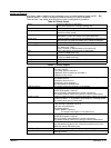
Wrn Fuel Level Warning threshold level for ANALOG INPUT 3.
Step: 1 %; Range: Sd Fuel Level − 10000
Sd Fuel Level Shutdown threshold level for ANALOG INPUT 3.
Step: 1 %; Range: −100 − Wrn Fuel Level
Fuel Level del Delay for ANALOG INPUT 3. Step: 1 s; Range: 0 − 180 s
Batt overvolt Warning threshold for high battery voltage.
Step: 0,1 V; Range: Batt undervolt − 40V
Batt undervolt Warning threshold for low battery voltage.
Step: 0,1 V; Range: 8V − Batt overvolt
Batt volt del Delay for low battery voltage alarm. Step: 1s; Range: 0 − 600 s
NextServTime Counts down when engine running. If reaches zero, an alarm appears.
Step: 1h; Range: 0 −65535h