


Operation 4-7
MN2417
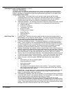
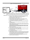
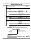
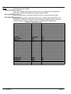
Meters, switches, lights and other operator control components are located in various places on
each panel. Figure 4-5 can be used to identify the function and features of each operator control
regardless of where it is located on your panel.
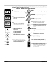
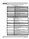
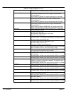
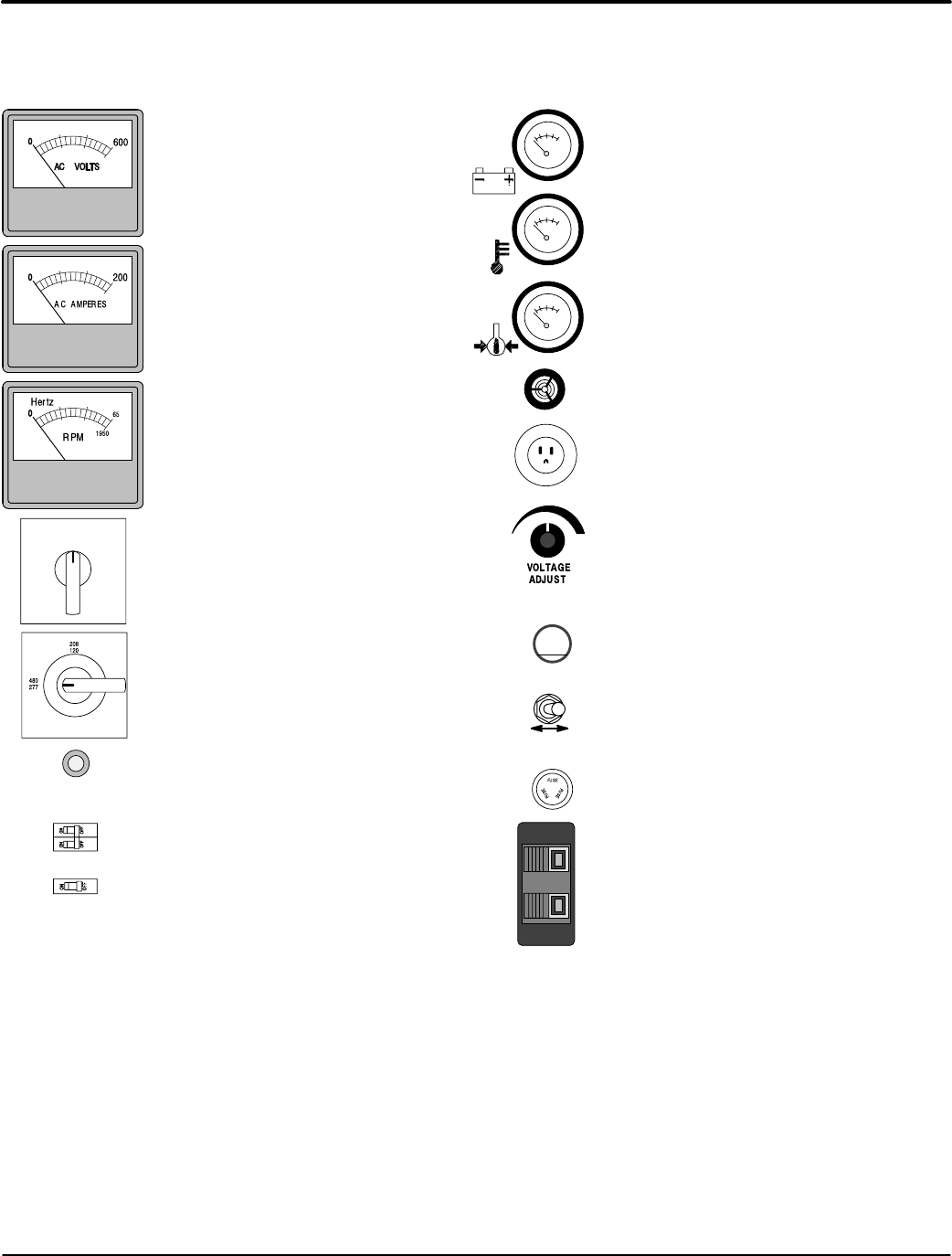
Figure 4-5 Operator Control Panel Components
PANEL LIGHTS
ON OFF
Panel Lights switch (On−Off )
Turns on the panel lights.
FUSE
Fuse Fuses provides protection on some units.
(Do not remove while generator is running).
BREAKER
Breaker Circuit Breakers provides protection on
some units. To reset a breaker, simply press
the center button when tripped or move
handle to Off" then back to On".
Shore Power Inlet Connect an extension cord that
has an appropriate rating from utility power to this
outlet. To power onboard battery charger, block
heater, etc.
Horn A Horn (annunciator or buzzer) sounds an
alarm when operator attention is needed.
Voltage Select Switch switch
Selects 208/120, 240/120 or 480/277VAC.
OFF
1
2
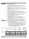
Auto Start Connection for external two wire starting from
transfer switch or other controller. Strip the
insulation from the remote start wires. Simply
press while inserting the wire then release to
secure the connection.
Panel Lights)
Lamps to illuminate the operator panel.
Amps Switch switch (On−Off )
Selects what is displayed on AC
Amperes meter.
Off − No AC Ampere display.
1 − Phase 1 current display.
2 − Phase 2 current display.
3 − Phase 3 current display.
Volts
Analog display of generator output voltage
in RMS volts.
AMPS
Analog display of generator output current
in RMS amps.
HERTZ
Analog display of generator RPM which
relates to the output frequency in Hertz.
Battery
Displays the voltage of the engine starting battery.
Water Temp
Displays the temperature of the engine coolant.
Oil Press
Displays engine oil pressure.
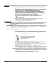
Voltage Adjust
Increase or Decrease the Generator output
voltage.
−+
or
or
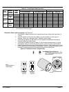
15
1 Pole
2 Pole