vii
LIST OF ILLUSTRATIONS
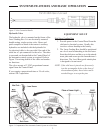
Figure 1. Plane of Laser Light with Components of the Automatic Control System ......................................1
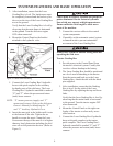
Figure 2. Valve Connection Details .................................................................................................................3
Figure 3. Components of the Automatic Control System on a Skid Steer .......................................................3
Figure 4. Control Panel Mounting ...................................................................................................................4
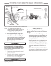
Figure 5. Components of the Automatic Control System on a Tractor ............................................................5
Figure 6. Method One: Align Rotating Laser with Grade Stakes ....................................................................6
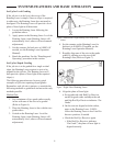
Figure 7. Sight Over Rotating Laser ................................................................................................................6
Figure 8. Grade Stake with Elevation Mark ....................................................................................................7
Figure 9. Method Two: Align Rotating Laser with Grade Stakes ....................................................................7
Figure 10. Lube and Maintenance Chart ........................................................................................................14


