


4
3. After installation, ensure that the Laser
Grading Box is level. The loader arms must
be completely lowered and the bucket cylin-
ders set so the tires of the Laser Grading Box
are on the ground.
Verify that the Laser Grading Box is level by
observing that the main frame is horizontal
to the ground. Turn the skid steer engine
OFF when connected.
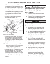
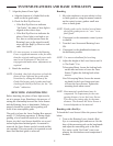
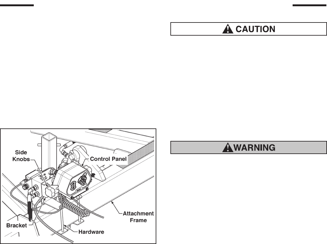
4. Mount the Control Panel on the bracket
attached to the hydraulic valve.
Figure 4. Control Panel Mounting
5. Connect the Laser Grading Box’s hydraulic
hoses with quick couplers to the auxiliary
hydraulic ports of the skid steer. The Laser
Grading Box’s hydraulic manifold is marked
“P” and “T” where the pressure and return
(tank) hoses connect.
NOTE: “P”meanspressure(supply)and“T”
meanstank(return).Refertotheskidsteer
Owner’sManualforidentifyingthe“P”
and“T”AuxiliaryHydraulicPorts.
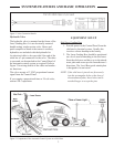
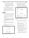
6. Insert the mast pole in the holder until it rests
at the bottom of the tube. Tighten the tee
handle to secure the mast. Clamp the Laser
Sensor near the top of the mast so it is higher
than any local obstruction including the skid
steer cab or fall protection devices. (Refer to
Figure 3).
Cables must be securely fastened and pinch/rub-
points eliminated. Do not fasten to hydraulic
lines which may operate at high temperatures.
Ensure sufcient cable length to allow move-
ment of the machine.
7. Connect the various cables to the control
system components.
8. If possible, set the automatic control system
to manual mode to prevent unintended
movement of the Laser Grading Box.
Always have system in Manual setting when not
operating the skid steer.
Tractor Grading Box
1. Provide power to the Control Panel from
the tractor's electrical system. Usually this
involves a direct hookup to the battery.
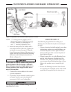
2. The Laser Grading Box should be positioned
on a level area for attaching to the tractor.
Start the tractor and back up to the Laser
Grading Box. Attach the unit with the hitch
pins supplied.
3. After installation, ensure that the Grading
Box is level. Set the pitch of the Laser
Grading Box by adjusting the top and lower
links.
Verify that the Laser Grading Box is level by
observing that the main frame is horizontal
to the ground. Turn the tractor engine OFF
when connected.
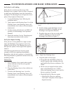
4. Mount the Control Panel on the right rear
fender of the tractor or other easily acces-
sible location.
5. Connect the Laser Grading Box’s hydraulic
hoses with quick couplers to the tractor
quick couplers. The Laser Grading Box’s
hydraulic manifold is marked “P” and “T”
where the pressure and return (tank) hoses
connect.
SYSTEMS FEATURES AND BASIC OPERATION