


1
PURPOSE
The Level Best Laser Grading Box is a cost-ef-
cient method for ne grading. Various capacities
sized to t the skid steer or tractor with a choice of
automatic control systems are available.
The Laser Grading Box is intended to operate with
an automatic control system providing accurate
grade control. If desired, the Laser Grading Box
can be operated without an automatic control
system in one of two ways:
Without any Valve/Manifold - The cylinder can
be connected directly to the tractor or skid
steer and the Laser Grading Box operated
using the tractor or skid steer valve. Flow to
the hydraulic cylinder is restricted to improve
control. However, movement of the cutting
edge can be coarse.
With the Valve and No Control System - A
switch can be installed to operate the electric
valve from the tractor or skid steer, providing
ne control of cylinder movement. However,
raising and lowering of the cutting edge is
dependant upon operator attentiveness and
accuracy.
For the most accurate control and ease of operation,
an automatic control system is used and recom-
mended. This manual is for a skid steer or tractor-
mounted, single cylinder Para-Level Laser Grading
Box with customer-supplied laser controls.
NOTE: Itistheresponsibilityofthedealeror
ownertoselect,install,andproperlyoper
-
ateanautomaticcontrolsystemonthis
LaserGradingBoxwithintheguidelinesof
thismanual.
Laser-guided depth control provides unmatched
measurement of plane from a single Rotating Laser.
Grade information from a Rotating Laser is pro-
cessed and automatically directs the grading box’s
hydraulics to maintain the elevation of the cutting
edge.
Most automatic control systems can operate auto-
matically or manually.
• In manual control, the operator watches an
indicator on the Laser Sensor or Control Panel
and uses the controls to keep the box “On
Grade”.
• In automatic control, the automatic control
system controls the box’s hydraulic cylinder to
keep the box “On Grade”.
COMPONENTS
The control system consists of 4 components:
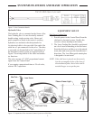
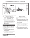
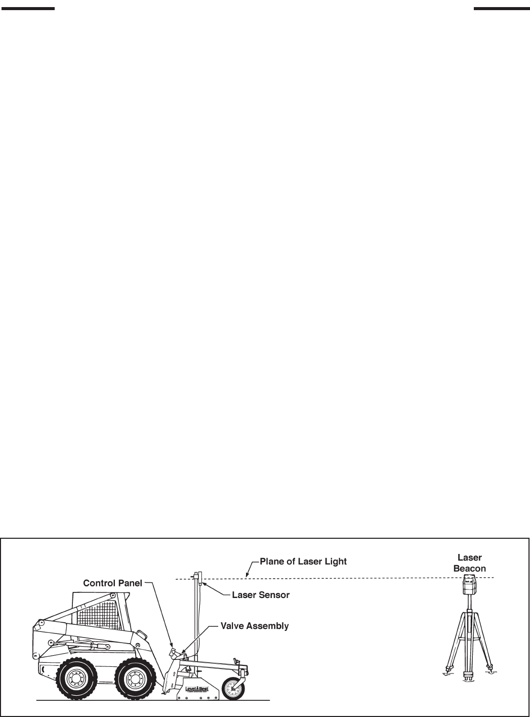
Rotating Laser – Provides a reference Plane of
Laser Light over the job site (refer to Figure 1).
Light plane may be level or set at an angle to
match the slope of the ground.
Laser Sensor – Mounted at a specic height on a
mast on the Laser Grading Box, it determines
the difference in depth based on the Plane of
Laser Light.
Figure 1. Plane of Laser Light with Components of the Automatic Control System
SYSTEMS FEATURES AND BASIC OPERATION