


5
NOTE: “P”meanspressure(supply)and“T”
meanstank(return).Refertothetractor
Owner’sManualforidentifyingthe“P”
and“T”AuxiliaryHydraulicPorts.
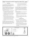
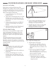
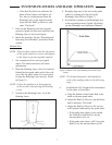
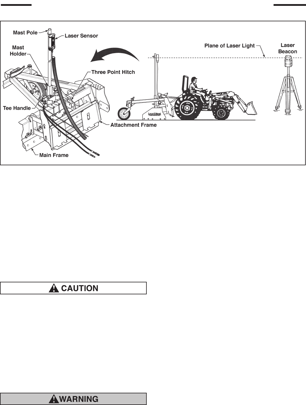
6. Insert the mast pole in the holder until it
rests at the bottom of the tube. Tighten the
tee handle to secure the mast. Clamp the
Laser Sensor near the top of the mast so it is
higher than any local obstruction including
the tractor cab or fall protection devices.
(Refer to Figure 5).
Cables must be securely fastened and pinch/rub-
points eliminated. Do not fasten to hydraulic
lines which may operate at high temperatures.
Ensure sufcient cable length to allow move-
ment of the machine.
7. Connect the various cables to the control
system components.
8. If possible, set the automatic control system
to manual mode to prevent unintended
movement of the Laser Grading Box.
Always have system in Manual setting when not
operating the tractor.
JOB SITE SET-UP
The following are guidelines for setting up a
Rotating Laser for both level job sites and sloped
job sites:
• Choose a location for the Rotating Laser where
obstructions, such as trees and buildings, can
not block the plane of laser light. The Laser
Sensor needs to be able to sense the plane of
laser light at all times.
• Whenever possible, set up the Rotating Laser
and the Laser Sensor at a height above the
machine’s cab. This prevents the cab or roll-
over structure from blocking the plane of laser
light as the machine moves around the job
sites.
• Be sure the Rotating Laser and Laser Sensor
are operating in compatible modes with a head
speed that is recognized by the other device.
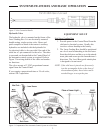
SYSTEMS FEATURES AND BASIC OPERATION
Figure 5. Components of the Automatic Control System on a Tractor