


8
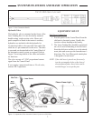
7. Align the plane of laser light.
a. Align the bottom of a Grade Rod to the
mark on the far grade stake.
b. Check the Rod Eye Receiver.
• If the Rod Eye Receiver indicates
“On Grade,” the plane of laser light is
aligned at the correct slope.
• If the Rod Eye Receiver indicates the
plane of laser light is too high or too
low, have a second person rotate the
Rotating Laser on the tripod in small
steps until the Rod Eye Receiver indi-
cates “On Grade.”
NOTE: IfitwasnecessarytorotatetheRotating
Laserasignicantamountatthefarstake,
thentheoriginalreadingatthenearstake
maybeoutoftolerance.Checktheset-
tingagainandmakeminoradjustmentsas
required.
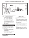
8. Bench the machine.
NOTE: Ifneeded,checktheelevationsonboththe
planeoflaserlightandthegradestake
elevationsbysettingthebottomofthe
GradeRodatanystake’sgrademarkand
checkingtheRodEyeReceiverforthe“On
Grade”indication.
BENCHING AND OPERATING
Before benching, the plane of laser light must be
set at its proper slope. Benching is the process of
setting the relationship between the Laser Sensor
and the Rotating Laser or benchmark. Failure to
properly bench the system before grading will
result in an unacceptable grade.
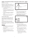
The goal is to have the Laser Grading Box approxi-
mately 1/2 full during operation. If, during rough
grading, a lot of material needs to be removed
from a site, the Laser Sensor should be set several
inches higher than nished grade. As material is
removed, the Laser Sensor can be lowered and the
site regraded. This may need to be repeated several
times until nished grade is achieved.
Benching
1. Move the machine to an area which is close
to nish grade or, using the manual controls
on the control system, grade a small area
close to nish grade.
NOTE:Finishgradecanbecheckedseveraltimes
duringthegradeprocessto“zero”inon
nalgrade.
2. If equipped, set the automatic control system
to manual.
3. Turn the Laser Sensor and Rotating Laser
ON.
4. If equipped, set the deadband tolerance to
the minimum possible.
NOTE: Usenarrowdeadbandforbenching.
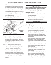
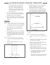
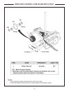
5. Adjust the height of the Laser Sensor until it
is “On Grade”. For:
Telescoping Masts, loosen the locking knob
on the mast and raise or lower the Laser
Sensor. Tighten the locking knob when
correct.
Non-Telescoping Masts, loosen the mount-
ing knob for the Laser Sensor and raise
or lower the Laser Sensor. Tighten the
mounting knob when correct.
NOTE: Mostmaterialsgradedmustlaterbe
compacted.Tocompensateforthecom
-
pactingdistance,lowertheLaserSensor.
Thisraisesthecuttingedgebythesame
distance.ThedistancetheLaserSensoris
lowereddependsonthematerial.
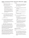
Benching with a Rod Eye
To bench the Laser Sensor follow the process listed
below:
1. Turn on the Rotating Laser. Attach a Rod
Eye to a measuring pole and turn on. Set the
base of the measuring pole on the benchmark
and adjust the measuring pole so the Rod
Eye emits a solid “On Grade” tone (com-
pensate for slab thickness and compaction if
needed).
SYSTEMS FEATURES AND BASIC OPERATION