


AR-EXP-CUMMINS-07-00 OWNERS MANUAL
Page 27
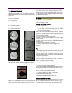
after the Safety On timer has expired, a shutdown is initi-
ated. The icon will flash.
NOTE:- The icon is used to indicate both underspeed
and overspeed. A flashing icon indicates underspeed. A
steady icon indicates overspeed.
7.2. SETTINGS
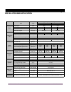
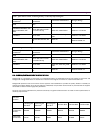
7.2.1 FIXED SETTINGS
The following settings are factory set and are NOT adjust-
able.
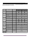
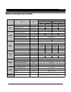
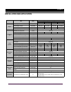
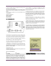
7.3 TERMINAL DESCRIPTION
NOTE:- All the outputs are solid state, rated at 1.2
Amps 8 Volts to 35 Volts DC, and switch to battery
negative when active.
Crank disconnect 20Hz
Underspeed 20Hz
Overspeed 57Hz (50Hz nominal)
68 Hz (60Hz nominal)
Remote start delay 5s
Preheat 10s
Crank period 10s
Crank rest 10s
Safety delay 10s
Remote stop delay 30s
PIN
No
DESCRIP-
TION
CABLE SIZE NOTES
1
DC Plant Sup-
ply Input (-ve)
1.0mm
Connected to
plant battery
negative
2
DC Plant Sup-
ply Input (+ve)
1.0mm
Connected to
plant battery
positive
(Recommende
d Fuse 2A)
3
Fuel relay Out-
put
0.5mm
Used to oper-
ate the fuel
solenoid con-
trol relay.
4
Start relay
Output
0.5mm
Used to oper-
ate the crank-
ing control
relay.
5
Preheat Out-
put relay
0.5mm
Used to oper-
ate the pre-
heat control
relay.
6
Remote Start
Input
0.5mm
Switch to
negative to
start set.
7
Charge Fail
Input/ Excita-
tion Output
1.0mm
Must NOT be
connected to
plant supply
negative if not
used.
8
Low Oil Pres-
sure Input
0.5mm
Switch to
negative on
fault.
9
High Engine
Temp Input
0.5mm
Switch to
negative on
fault.