


AR-EXP-CUMMINS-07-00 OWNERS MANUAL
Page 14
4. ELECTRICAL SYSTEM
There are a number of different generator systems and
typical loads in the context of electrical systems. Most sys-
tems, unless they contain automated switch gear, have a
means of disconnect between the generator and the
load. This is typically a transfer switch or discon-
nect. Ensure the contacts on the switch are rated for the
size of your system.
4.1. GENERAL ELECTRICAL SYSTEM
When mounting electrical panels, a 3 foot clearance is re-
quired and the use of an emergency light to illuminate the
unit during operation is typically required. Power for the
emergency light should be from both the primary utility and
the generator. This is highly recommend so that in the event
of a malfunction there is a light source to see to work on the
unit. Refer to your local building and electrical codes to
ensure compliance.
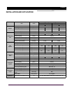
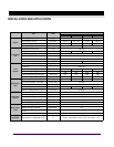
4.2. CONDUCTOR SIZING CONNECTION
This information is dependent upon your generator output
and intended load. When connecting cables to the genera-
tor, make connections at the generator first. Make the con-
nections at the load last. Failure to do so may constitute a
fire or safety hazard.
All ampacities are typically calculated at 75
o
C (Celsius)
(167
o
F(Fahrenheit) in the conductor size charts. Building
wire conductors should be rated at 90
o
C(194
o
F) to allow for
different ambient temperatures that these conductors may
pass through.
All conductors are typically required by electrical code to be
copper. The recommended conductor sizes are based on
maximum current. Ampacities are found in NEC Article 310,
Table 310-16. Conductor resistances are found in NEC Ta-
ble 8 "Conductor Properties".
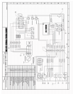
4.3. CONNECTING THE GENERATOR
Please the refer to the electrical drawing of the unit and
your transfer switch documentation for information related.
Leave the installation only to a trained personnel and don’t
forget to observe the local laws and permit requirements.
Errors during the installation may damage the equipment
and electrical devices connected to the unit and may create
fire and electrocution risks.
5. EXHAUST SYSTEM
5.1. GENERAL (EXHAUST SYSTEM)
Generator engines give off deadly carbon monoxide gas
through their exhaust systems.
Carbon monoxide gas, if breathed in sufficient concentra-
tions, can cause unconsciousness or death. Exhaust gases
must be piped safely away from any room or enclosure that
houses a generator and to a well ventilated area where
people will not be endangered.
Besides the possibility of carbon monoxide poisoning, ex-
haust piping becomes extremely hot during operation and
remains hot for a long time after shutdown. For that reason,
the following precautions are necessary:
• Avoid contact with hot engines, exhaust manifolds,
exhaust piping and mufflers. Any of these can cause
severe burns.
• Where piping must pass through combustible walls or
ceilings, special precautions must be taken to prevent
fire or heat damage such as using heat thimbles
through walls and ceilings.
5.2. GENERAL RULES FOR EXHAUST SYSTEM
When installing an exhaust system for a generator, the fol-
lowing rules should be considered:
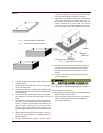
• Exhaust piping should be of wrought iron or steel hav-
ing adequate strength and durability.
• Exhaust fittings may be of cast iron. A 9 inch spacing
(10 inches (250mm) recommended) from the exhaust
pipe and walls is also required by most local codes.
• Low points in horizontal runs of piping should be pro-
vided with condensation traps, as well as condensation
drains.
• Piping and mufflers must be properly supported and
connected.
• A flexible length of exhaust pipe is required between
the engine exhaust manifold and rigid exhaust piping.
• Exhaust piping must be terminated safely outside a
structure that houses a generator, in such a way that
hot gases and sparks will be discharged harmlessly
and will not blow against any combustible surface or
material.
• Exhaust piping must not terminate under loading plat-
forms, structures, or near any opening in a building.
• Where necessary, exhaust piping must be guarded
and/or insulated to prevent burns.
• Provide a clearance of at least 9 inches (229mm)(10
inches (250mm) recommended) between exhaust
piping and any combustible material.
• Keep exhaust piping well clear of fuel tanks, fuel lines,
etc.
5.3. RAIN CAP
A rain cap is recommended on the end of the exhaust pipe.
The rain cap is attached to the end of the pipe and opens
due to the pressure from the exhaust discharge force. The
rain cap protects the exhaust system from the environment
when the system is not running.
5.4. SPARK ARRESTOR
Use of a spark arrestor is required by the U.S. Department
of Forestry if located on lands under their jurisdiction. The
spark arrestor is recommended in areas where combustible
materials may ignite such as dry grass, leaves, or other
combustible materials.