


GB - 9
ASSEMBLY
Tools Required:
• Pliers
• Open-End Wrenches: 3/8, 7/16, 1/2,
9/16 in. and/or Adjustable Wrench
•Tire Gauge
• Torque Wrench (Optional)
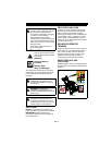
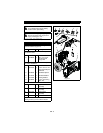
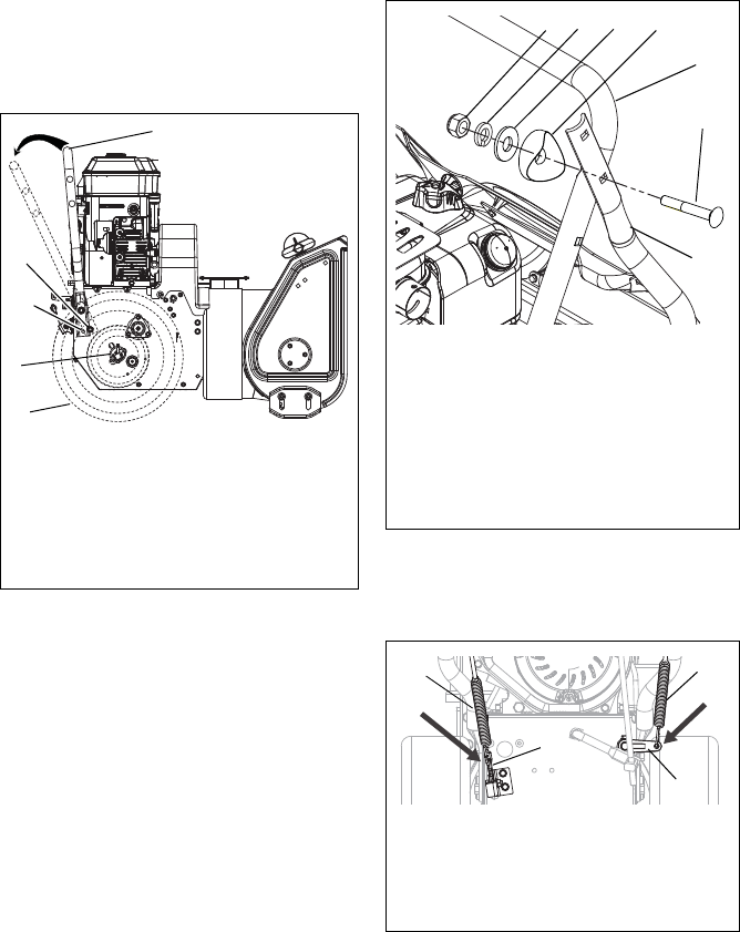
Unfold Lower Handlebar
(Figure 4)
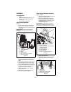
1. Remove wheel pins from each side of
the unit and slide wheels away from
frame (Figure 4). Do not remove wheels
completely.
IMPORTANT: Be sure to block wheels or
secure unit so it does not move during
assembly.
.
2. Remove 3/8 in-16 x 3/4 in. serrated
head flange bolt from the mounting
holes on each side of the frame. Keep
bolts.
3. Rotate lower handlebar out from unit so
lower handlebar mounting holes align
with mounting holes on the unit frame.
4. Secure lower handlebar to unit using the
two 3/8 in-16 x 3/4 in. serrated head
flange bolts removed in step 2.
5. Tighten all four bolts to 25 – 42 lbf-ft
(33.9 – 56.9 N•m)
6. Slide wheels on both sides back into
place and reinstall wheel pins.
Attach Upper Handlebar Assembly
(Figure 5 and 6)
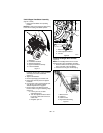
1. Remove handlebar hardware from lower
handlebar. Keep hardware.
2. Attach upper handlebar assembly to
lower handlebar using two sets of the
handlebar hardware removed in step 1.
One set to attach each side of the
handlebars (Figure 5).
IMPORTANT: DO NOT tighten hardware.
Allow upper handlebar assembly to hang
from the lower handlebars for the next step.
.
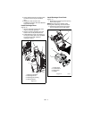
3. Hook spring end of attachment control
cable to the clutch arm.
4. Hook spring end of the traction control
cable to the cable eyelet on back of
frame.
.
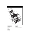
Figure 4
2
1
3
1. Lower Handlebar
2. Wheel Pin
3. Wheel
4. Mounting Hole
5. 3/8 in-16 x 3/4 in. Serrated
Head Flange Bolt
5
4
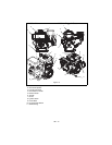
Figure 5
3
4
2
1. Upper Handlebar Assembly
2. Lower Handlebar
3. 5/16 in-18 x 2-1/4 in. Round Head
Square Neck Bolt
4. Handlebar Spacer
5. Flat Steel Washer
6. Locking Washer
7. 5/16 in-18 Locking Nylon Nut
1
7
6
5
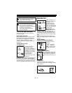
Figure 6
3
1. Clutch Arm
2. Cable Eyelet
3. Attachment Control Cable
4. Traction Control Cable
1
4
2