


GB - 31
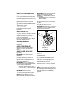
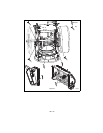
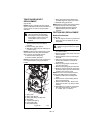
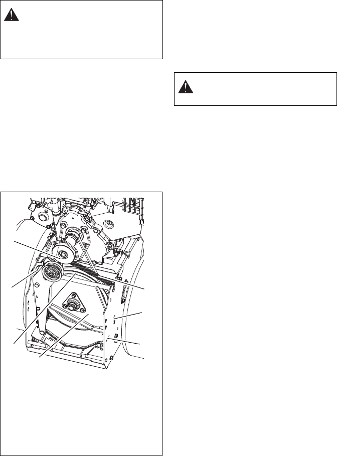
TRACTION DRIVE BELT
REPLACEMENT
(Figures 38)
NOTE: Housing and frame must be tipped
apart and attachment drive belt removed from
engine sheave in order to change traction
drive belt.
1. Remove attachment drive belt (See
Remove Attachment Drive Belt on
page 29).
2. Remove swing gate spacer.
3. Slide drive plate to the left until finger is
out of the frame.
NOTE: The drive plate is detached to create
space between the drive plate and friction
disc to remove and reinstall the belt.
4. Detach traction idler spring.
5. Remove traction drive belt.
NOTE: To remove belt it may be necessary to
turn crankshaft pulley using recoil starter
handle.
6. Replace traction drive belt.
7. Swing drive plate toward friction disc
and slide finger into stop hole in frame.
8. Reinstall swing gate spacer.
NOTE: Make sure drive plate spring remains
connected to the frame and drive plate.
9. Replace attachment drive belt (See
Replace Attachment Drive Belt on
page 30).
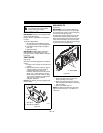
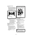
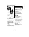
FRICTION DISC REPLACEMENT
Remove Friction Disc
(Figure 39)
1. Shut off engine, remove key, disconnect
spark plug wire and allow unit to cool
completely.
2. Place the unit into the service position
on a level surface.
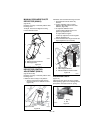
3. Remove lockpins from wheel axles and
remove wheels.
4. Remove bottom cover by removing six
hex bolts.
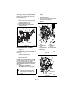
5. Disconnect pivot pin from the speed
selector arm. Save the hardware for
reinstallation.
6. Remove spring hairpin nearest drive
gear from hex shaft.
7. Remove left bearing flange from frame.
8. Slide hex shaft to the left to remove the
flat washer, pinion gear and friction disc
assembly from the hex shaft.
NOTE: Be sure to save washers between
bearing and sliding fork for reassembly.
9. Remove friction disc assembly from
frame.
10. Remove three screws holding friction
disc to carrier bearing.
11. Remove old friction disc. Put the new
friction disc in place, cup side to carrier
bearing.
12. Reinstall three screws into new friction
disc and carrier bearing. Torque to
5 – 6 lbf-ft. (6.8 – 8.13 N•m).
CAUTION: Always support Sno-Thro
frame and blower housing when
loosening the cap screws holding
them together. Never loosen cap
screws while unit is in service
position.
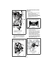
Figure 38
1. Swing Gate
2. Swing Gate Spacer
3. Swing Gate Finger & Stop Hole
4. Drive Plate
5. Traction Idler Spring
6. Crankshaft Pulley
7. Drive Plate Spring
4
2
3
5
6
7
1
OS8246
CAUTION: Before tipping unit,
remove enough fuel so that no spills
occur.