


GB - 29
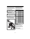
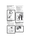
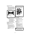
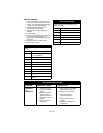
Check Attachment Brake
(Figure 33)
1. With the clutch lever disengaged, brake
pad must contact attachment belt. With
clutch lever engaged, brake pad must be
more than 1/16 in. (1.6 mm) from belt. If
there is more than 1/16 in. (1.6 mm) gap,
go to Check Belt Finger Clearance on
page 29. If there is less than 1/16 in. (1.6
mm) gap, go to Step 2.
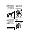
2. If there is less than 1/16 in. (1.6 mm)
gap between brake pad and belt, follow
these steps:
a. To increase brake pad gap,
loosen idler adjustment nut, and
move idler away from belt.
Position idler to achieve a 1/16 in.
(1.6 mm) minimum brake pad gap
and a 1/2 – 7/8 in. (12.7 –
22.2 mm) gap between the
plastic roller and the frame.
IMPORTANT: If adjustments cannot be
brought into specified ranges see your Dealer
for repairs.
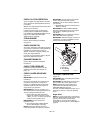
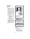
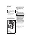
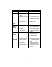
Check Belt Finger Clearance
(Figure 34)
1. With clutch lever engaged, the belt
finger located opposite the belt idler
must be less than 1/8 in. (3,2 mm) from
belt, but not touching the belt.
To adjust belt finger, loosen the bolts and
move the finger to the proper position.
Tighten the bolts and recheck the belt
finger clearance.
2. Replace the belt cover and tighten
hardware.
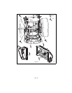
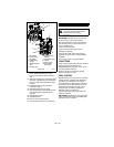
ATTACHMENT DRIVE BELT
REPLACEMENT
Remove Attachment Drive Belt
(Figures 35, 36 and 37)
1. Shut off engine, remove key, disconnect
spark plug wire and allow unit to cool
completely.
2. Loosen the hardware securing belt
cover to unit.
NOTE: DO NOT completely remove the
hardware from unit.
3. Remove belt cover.
4. Remove hairpin from chute crank and
separate.
5. 920014 – Remove remote deflector
control cable from dash control.
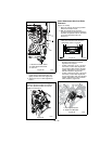
6. Remove belt finger by removing cap
screws mounting belt finger to engine
(Figure 36 or Figure 37).
7. Remove attachment drive belt from
engine sheave (it may be necessary to
turn engine sheave using recoil starter
handle).
Figure 33
Minimum of 1/16 in. (1.6 mm)
1. Brake Arm and Pad
2. Attachment Pulley
1
2
OS8260
CAUTION: Always support Sno-Thro
frame and housing when loosening
the cap screws holding them
together. Never loosen cap screws
while unit is in service position.
Figure 34
Check belt finger clearance here. With the
attachment clutch engaged, there should
be less than 1/8 in. (3,2 mm) clearance
between the belt and the belt finger. The
belt finger should not touch the belt.
OS8240