


MAINTENANCE
Maintenance Section 5-6
© 2005 Alamo Group Inc.
GRIZZLY 66 01/05
Blade Arm
1. The taper fit between the Blade Arm and the shaft must be blued and checked. Only perfect fits are acceptable
-- reject anything less.
2. Warm Blade Arm to 180-200 degrees C.
3. Slip Blade Arm on shaft and tighten nut to 500ft/lb (27 on torque multiplier).
4. Allow Blade Arm to cool to ambient temperature.
5. Remove nut, apply Never Seize or equivalent to the thread and re-torque per Table 4.
Never Hammer Blade Arm
Blade Bolts
1. Make sure washer is right side up with the relief of the washer clearing the radius of the bolt.
2. Apply Never Seize or equivalent to threads of Blade Bolt.
3. Use Stover Lock Nut.
4. Torque to required value as per Table 4.
(TABLE 4)
Blade Arm & Bolt Torque Values
52"PBC 1 1/2"-12NF 1200-1300 ft/lb 65-70 on torque multiplier
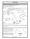
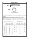
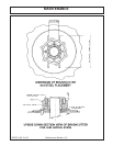
Installation & Removal of Locking Assembly
Installation
Locking assembies are supplied ready for installation. However, if for some reason locking assemblies with
odd number of screws were disassembled, make sure that in addition to lined-up slits in all collars, near -and
far-side clamp collars are not reversed. They are assembled correctly only if there are no holes or threads
behind taps in clamp collar item "1". Likewise, there must be no threads behind taps in center collar item "3"
as illustrated in Figure 1.
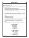
Motor Mounting Plate
NOTE: The Motor Mounting Plate must be true to shaft to prevent excessive wear on couplings and splined
inserts.
1. The surface of the shroud and motor mount plate must be flat with no rocking allowed.
2. Clamp and dial in Motor Mounting Plate to Grizzly Housing Shaft.
3. Drill 4 holes for mounting bolts.
4. Bolt Motor Mounting Plate to shroud and check run out. Adjust position of plate to meet tolerances for
maximum indicated run out. See Table 3.
5. Drill and ream dowel holes.
6. Install insert and snap ring. Fill insert with 10 pumps of grease.
7. Install Motor. Torque to required values and wire lock heads.
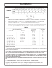
Motor Mounting Plate
Face of Plate .008"
Bore of Plate .004"
(TABLE 3)
Maximum indicated run out