


ASSEMBLY
Assembly Section 3-2
© 2005 Alamo Group Inc.
GRIZZLY 66 01/05
PRE-INSTALLATION
Prior to installing the Girzzly on the carrier, check to make sure that the combination of carrier and Grizzly is correct
and is as ordered.
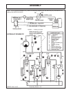
INSTALLATION
The cutter requires a constant flow of hydraulic oil and must be provided with a supply that will not be reduced
when another function of the machine is used simultaneously.
The control valve must be of the motor spool type that will allow the Grizzly to gradually slow to a stop rather than
"lock up" when the control is moved to the "OFF" position. If a motor spool equipped control valve cannot be
provided then a system of circulating check valves must be used in the vicinity of the drive motor.
The control valve may be electically operated, (HED or STANLEY type), or pressure compensated manual, (Char
Lynn etc.). Some operators prefer a dual direction Parker valve, (PARKER #VS 32ACA9).
The drive motor must be provided with a cross over relief valve to protect it from pressure spikes if the blades
strike a rock, stump or other immovable object.
If dual rotation is preferred, a dual action cross over relief valve is required.
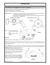
A drain line must be installed from the motor case to the tank. The case drain is provided to prevent oil from
building up behind the output shaft seal. This is particularly important when dual rotation is used. If possible
connect the drain line to the upper part of the tank.
The case drain line must be minimum 1/2" single braid to prevent the line from being crimped, thus shuting off the
oil flow. There is, normally, very little pressure in this line, however it must remain open to allow any oil behind the
seal to escape.
Hydraulic line sizes are important. Pressure lines should be minimum 1" double braid hydraulic lines. The return
line must also be 1" but need only be single braid. Note that if dual rotation is used both lines become pressure
lines so they both must be double braid.
The maximum oil pressure permitted with the low pressure gear type motor is 2000 p.s.i. The control valve should
be equipped with a pressure relief valve set below 2000 p.s.i.
NOTE:
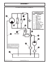
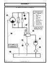
On medium pressure machines a modified gear type motor may be used allowing pressures up to 2500 p.s.i. High
pressure machines use a high pressure piston type motor. This motor is capable of operating at 3500 p.s.i. with
a correspondingly lower flow rate.
CAUTION! The Grizzly control valve must not be engaged at high engine RPM. When dual direction control is
used, the direction of rotation must not be changed until the cutter head has slowed to a stop.
NOTE: RPM LIMITATION
The shaft speed of the Grizzly must not, under any circumstances, exceed 1800 RPM . Operation in excess
of this maximum RPM may result in damage to component parts and is a safety hazard.
PRECAUTIONS