6
JJ
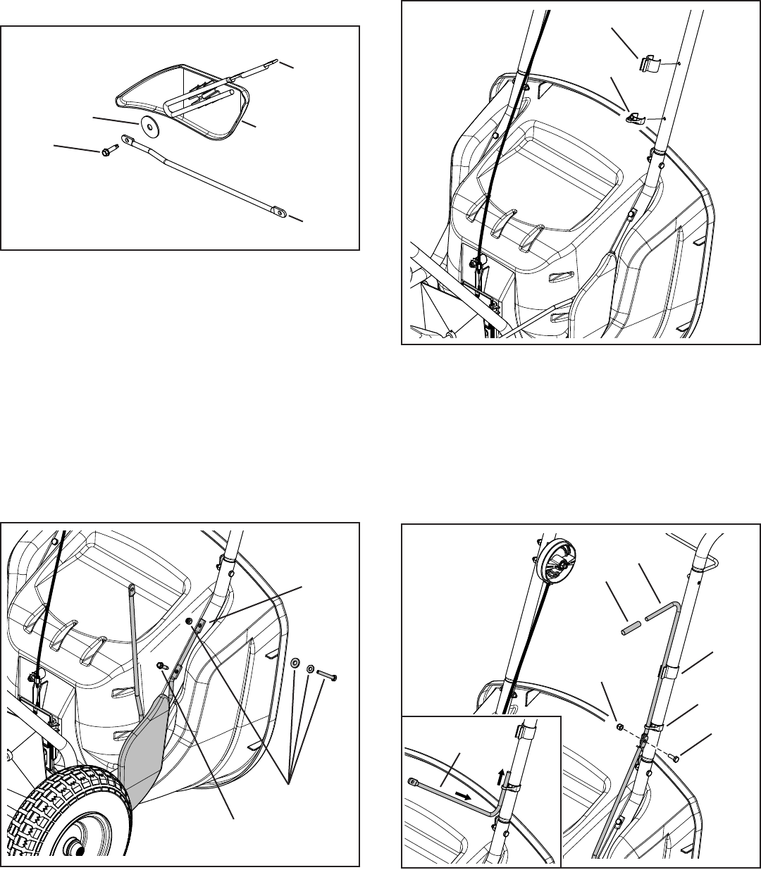
FIGURE 9
FIGURE 10
KK
LL
FF
DD
KK
JJ
G
G
GG
F
I
H
EE
EE
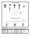
ORIGINAL
FASTENERS
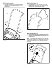
STEP 7: (SEE FIGURE 7)
THIS STEP FOR MODEL 45-0471 ONLY
• Assemblethedeectorrod(I),washer(GG),and
connectingrod(H)tothedeector(F)usingthe
threadformingscrew(EE).Tightenthescrewuntilit
isjustsnugandthenbackitoff1/4turnoruntilthe
deectorrod(H)willslidefreely.
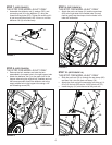
STEP 8: (SEE FIGURE 8)
THIS STEP FOR MODEL 45-0471 ONLY
• Removethebolt,washersandnutsthatare
assembledintheupperholeintherighthoppertube.
• Attachthedeectorrod(I)totheupperholeinthe
hoppertubeusingtheoriginalbolt,washersandnut
thatwereremoved.Attachthedeectorrodtothe
emptymiddleholeinthehoppertubeusinga1/4"
selfthreadingscrew(EE).
FIGURE 7
FIGURE 8
I
STEP 9: (SEE FIGURE 9)
THIS STEP FOR MODEL 45-0471 ONLY
• Attachthepushrodclamp(JJ)andtheeyeclamp
(KK)totherightsideofthehandletube.Youmay
needtogentlytaptheclampsintotheholesinthe
tubewithahammer.
STEP 10: (SEE FIGURE 10)
THIS STEP FOR MODEL 45-0471 ONLY
• Slidethepushrod(G)upthroughtheeyeclamp(KK)
andthenclipitintothepushrodclamp(JJ).
• Attachthepushrodtotheconnectingrodusinga1/4-
20x3/4"hexbolt(DD)anda1/4-20nylocknut(FF).
• Installthegrip(LL)ontotheendofthepushrod.


