


5
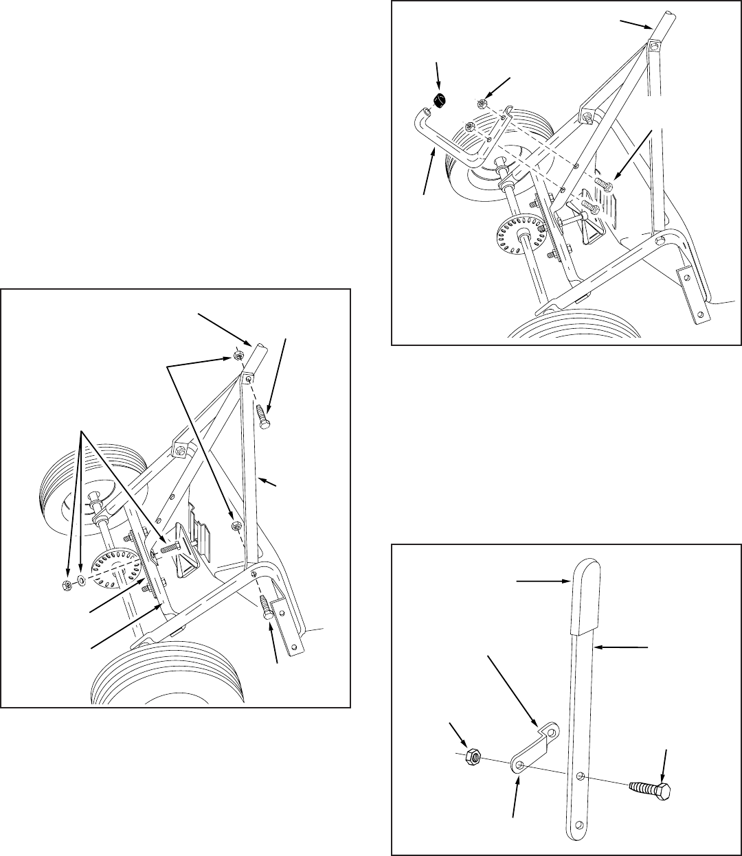
FIGURE 6
FLOW CONTROL
LINK
VINYL GRIP
FLOW
CONTROL
ARM
1/4" x 5/8"
HEX BOLT
SMALL HOLE
1/4" HEX
LOCK NUT
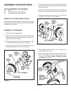
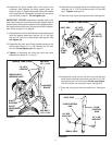
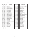
14. Assemble the leg stand tube to the handle tube (long)
using two 1/4" x 1-1/2" hex bolts and two 1/4" hex lock
nuts. Tighten. See figure 5.
15. Place the vinyl cap on the leg stand tube. See figure 5.
16. Assemble the flow control link (the long end with the
small hole) to the flow control arm using one 1/4" x 5/8"
hex bolt and one 1/4" hex lock nut. Do not over tighten.
The flow control link must pivot freely. See figure 6.
17. Place the vinyl grip on the flow control arm. See figure
6.
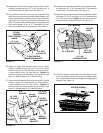
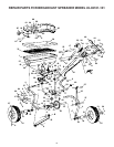
10. Assemble the (long) handle tube to the side of the
crossover tube opposite the shaft support plate, as
shown in figure 4. Fasten the handle tube to the middle
hole using the bolt, flat washer and hex lock nut which
you removed in step 9. Do not tighten yet.
IMPORTANT: DO NOT assemble the handle tube to the
side of the crossover tube where the shaft support plate is
located. When the spreader is placed in the upright position,
the handle tube must be on to the top side of the crossover
tube. Refer to figure 17 on page 9.
11. Assemble the end of a handle brace to the inside of each
leg of the hopper tube frame, using a 1/4" x 1-3/4" hex
bolt and 1/4" lock nut for each brace. See figure 4. Do
not tighten yet.
12. Assemble the other end of both handle braces to the
handle tube using a 1/4" x 1-3/4" hex bolt and 1/4" hex
lock nut. Do not tighten yet. See figure 4
13. Tighten in sequence the bolts and nuts that were
assembled in steps 10, 11 and 12.
FIGURE 5
HANDLE TUBE (LONG)
1/4" HEX
LOCK NUT
VINYL CAP
LEG
STAND
TUBE
1/4" x 1-1/2"
HEX BOLTS
HANDLE TUBE (LONG)
HEX BOLT
1/4" x 1-3/4"
HEX BOLT
1/4" x 1-3/4"
HANDLE
BRACE
SHAFT
SUPPORT
PLATE
MIDDLE BOLT,
WASHER & NUT
1/4" HEX
LOCKNUT
CROSSOVER
TUBE
FIGURE 4