CM9740-CC1 | 3
LIST OF ILLUSTRATIONS
Figure Page
1 CM9740-CC1 Front View ................................................................................... 8
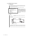
2 Rear View, General Identification ....................................................................... 9
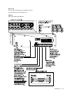
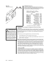
3 CM9740-CC1 Rear Connector Pinouts ............................................................. 11
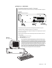
4 Multiple Receiver Hook-up ................................................................................11
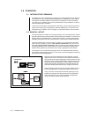
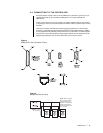
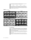
5 Category I–Bare Bones .....................................................................................12
6 Category I–Fleshed Out .................................................................................... 12
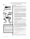
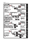
7 Single-Node Initialization .................................................................................. 16
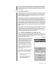
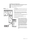
8 Initialization–System Window ............................................................................17
9 Initialization– Configuration File ........................................................................ 17
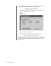
10 Initialization–Online Nodes ............................................................................... 18
11 MGR Windows–A Precaution ............................................................................18
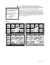
12 Single-Node Hot Switch Configurations ............................................................ 19
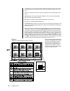
13 Display Screen Geometry ................................................................................. 21
14 Diagnostic Screen and Monitor Box Geometry .................................................22
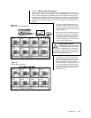
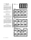
15 Monitor Box Camera Switching ......................................................................... 23
16 Monitor Box Preset Call .................................................................................... 23
17 Monitor Box Allocation ...................................................................................... 24
18 Monitor Box–F1 Allocation ................................................................................ 24
19 Monitor Box–Allocate 3 to 1 .............................................................................. 24
20 Monitor Box Switch ........................................................................................... 24
21 Keys Command–Examples ...............................................................................26
22 Time Synchronization ....................................................................................... 27
23 Configuration File Dialog Box ............................................................................29
24 Hard Drive Update ............................................................................................ 30
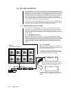
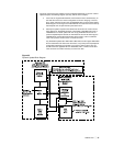
25 Dynamic Update Block Diagram .......................................................................31
26 Sample AUTOEXEC.BAT File ...........................................................................35
27 CC1 Connections–Exercise I ............................................................................45
28 CC1 Setup–Final............................................................................................... 45
29 CC1 Directory Structure .................................................................................... 47
30 Root Directory ................................................................................................... 47
31 9740 Directory................................................................................................... 47
32 The DOS Directory............................................................................................ 48
33 TESTPORT Directory ....................................................................................... 50
34 MGR Program Location .................................................................................... 51