


15
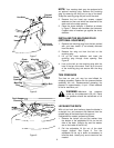
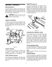
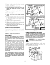
4. Loosen the hex nut on the scissor mounting
bracket. See Figure 17.
5. Start the engine and run at full throttle.
6. Move the hydrostatic control lever until you find
neutral (rear wheels do not rotate in either
direction).
7. Depress the clutch-brake pedal until the scissor
brackets come together.
8. Shut off the engine.
9. Tighten the hex nut on the scissor mounting
bracket
10. Thread the speed selector rod in or out of the
ferrule until the hydrostatic control lever lines up
in the neutral position on the speed control
index bracket.
11. Tighten hex jam nut against the ferrule.
12. Replace the transmission panel, parking brake
knob and rubber boot on relief valve.
13. Remove the blocks from under the frame and
test the operation of the tractor.
DECK LEVELING ADJUSTMENT
If an uneven cut is obtained, the deck may be
leveled by following instructions in the Assembly
section.
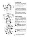
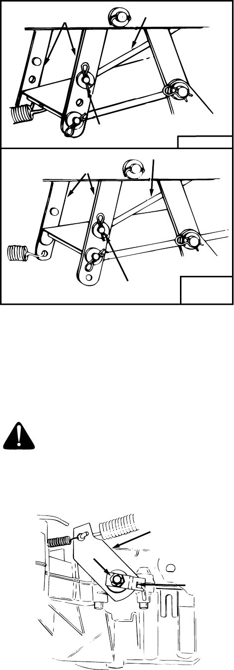
CUTTING DECK ENGAGEMENT
ADJUSTMENT
The cutting deck engagement may be adjusted to
make certain deck is disengaged when lift lever is in
the BLADES STOP position. Correct adjustment as
follows.
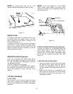
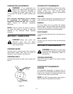
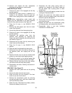
With the engine off, place the lift lever in the highest
cutting position (first position). Remove the cotter
pin and flat washer which secure the
disengagement rod to the stabilizer shaft assembly.
See Figure 18. Shorten the rod by threading it in,
until the ferrule is against the back of the slot in the
lift shaft assembly, and the rod lines up with the
hole in the stabilizer shaft. For more belt tension the
disengagement rod must be lengthened. To
decrease belt tension the disengagement rod must
be shortened.
Check the adjustment by placing the lift lever in the
BLADES STOP position. The deck should move up
and forward, allowing the belt to become loose.
Start and test for disengagement. Repeat procedure
as necessary.
Figure 18
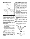
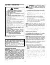
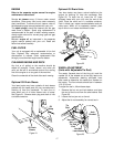
BRAKE ADJUSTMENT (See Figure 19)
The brake is located by the right rear wheel inside
the frame. The brake has been set at the factory to
the proper clearance. During normal operation of
this machine, the brakes are subject to wear and
will require periodic examination and adjustment.
WARNING: Do not have the engine
running when you adjust the brake.
To adjust the brake, adjust the nut so the brake
starts to engage when the brake lever is 1/4" to
5/16" away from the axle housing.
Figure 19
38" Decks
42" and
46"Decks
Stabilizer Shaft
Assembly
Disengagement Rod
Flat Washer
Hairpin Clip
Stabilizer Shaft
Assembly
Disengagement Rod
Flat Washer
Hairpin Clip
Nut
Brake
Lever
Disc
Brake