


SECTION5: KNOWYOURGARDENTRACTOR
This section ismeant to acquaint you with the various types ofcontrols and switches available on these tractors.
Please read this section carefully and know your tractor better before startingto operate it. As with any power
equipment, it is extremely important to ensure proper and safe operation ofthe tractor by following the instructions
closely. Note that this manual covers various models and many controls, listed here, may be optional items.
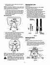
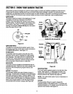
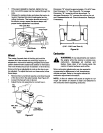
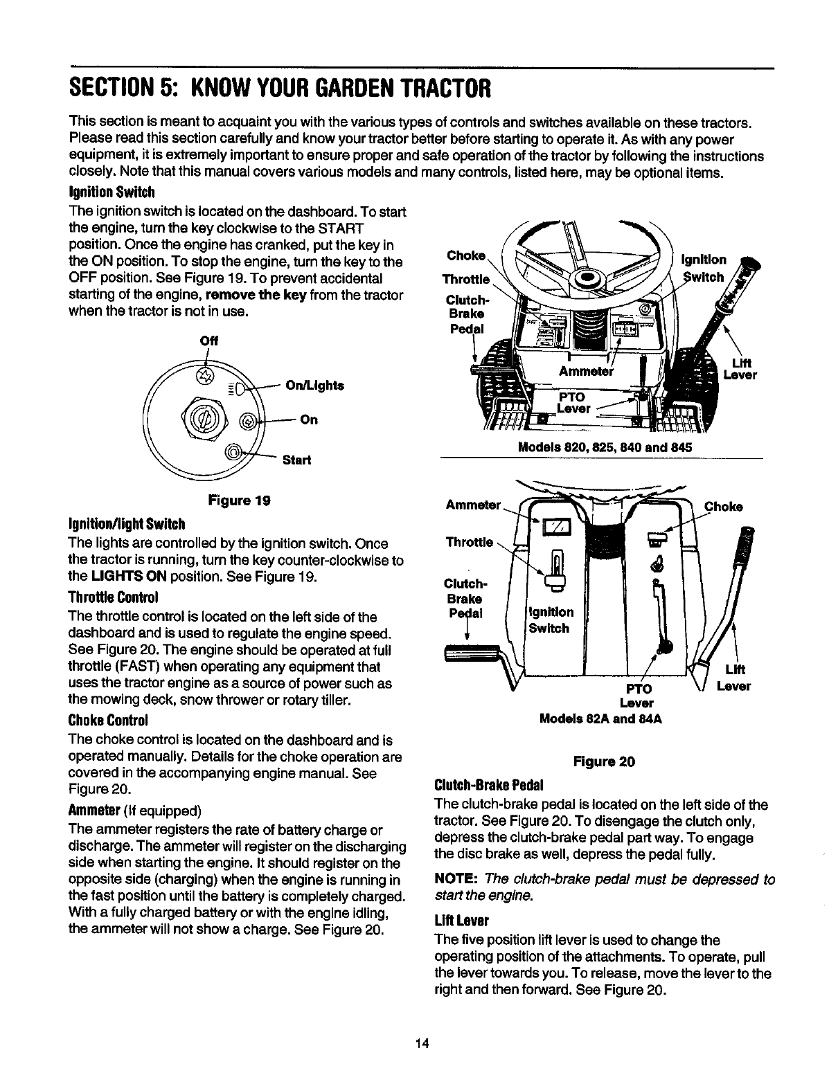
IgnitionSwitch
The ignition switch is located on the dashboard. To start
the engine, turn the key clockwise to the START
position. Once the engine has cranked, putthe key in
the ON position. To stop the engine, turn the key to the Choke\ Ignition
OFF position. See Figure 19. To prevent accidental Throttle
\
starting of the engine, remove the key from the tractor Clutch-
when the tractor is not in use. Brake
Off
Lever
Models 820, 825, 840 and 845
Figure 19
Ignitlon/ligM Switch
The lights are controlled by the ignition switch. Once
the tractor isrunning, turn the key counter-clockwise to
the LIGHTS ON position. See Figure 19.
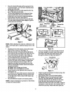
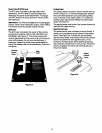
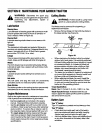
Throttle Control
The throttle control is located on the left side of the
dashboard and is used to regulate the engine speed.
See Figure 20. The engine should be operated at full
throttle (FAST) when operating any equipment that
uses the tractor engine as a source of power such as
the mowing deck, snow thrower or rotarytiller.
ChokeControl
The choke control is located on the dashboard and is
operated manually. Details for the choke operation are
covered in the accompanying engine manual. See
Figure 20.
Ammeter(If equipped)
The ammeter registers the rate of battery charge or
discharge. The ammeter willregister on the discharging
side when starting the engine. It should register on the
opposite side (charging) when the engine is running in
the fast position untilthe battery is completely charged.
With a fully charged battery or with the engine idling,
the ammeter will not show a charge. See Figure 20.
Ammeter Choke
Clutch-
Brake
Pe_al
Fro
Lever
Models 82A and 84A
Lift
Lever
Figure 20
Clutch-BrakePedal
The clutch-brake pedal is located on the left side of the
tractor. See Figure 20. To disengage the clutch only,
depress the clutch-brake pedal part way. To engage
the disc brake as well, depress the pedal fully.
NOTE: The clutch-brake pedal must be depressed to
start the engine.
Lift Lever
The five position lift lever is used to change the
operating positionof the attachments. To operate, pull
the lever towards you. To release, move the lever to the
right and then forward. See Figure 20.
14