


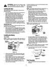

,_ WARNING: Maximum tire pressure under
any circumstances is 30 p.s.i. Equal tire
pressure should be maintained on all tires.
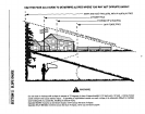
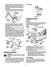
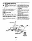
Leveling the Deck
After attaching the deck to the tractor, make sure it is
adjusted properly.
• Check tire pressure of all four tires. See sidewall of
tire for recommended inflation pressure.
• Make certain all deck wheels or both ends of the
deck rollerare mounted in same relative hole
locations.Place the tractor on a level surface.
46" Deck: Lower the deck until it reaches the
ground. All four deck wheels should reach the
ground at the same time.
Place the deck approximately 1" above the ground.
The distance from the bottom edge of the deck to
the ground must be same on both sides of the deck.
AdjustingDeck Links
If adjustment isnecessary, adjust the deck links on the
left side of the deck as follows.
• Make certain the PTO isdisengaged. Remove hairpin
clip and washer from the weld bolt.Thread eyebolt up
or down the linkas necessary, and reassemble.
• Make sure that the front of the deck is l /4" to 3/8"
lower than the rear of the deck. If it is not, adjust the
two front links to obtain this distance.
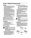
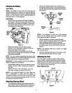
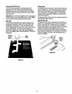
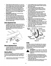
Installingthe Battery
Type ABattery
NOTE: If battery is put into service after date shown on
top of battery, charge for minimum I hour at 6-10 amp&
Positive
Cable Neget ve
Terminal
(Black)
Flgure 16
• Liftthe hood of the tractor. Remove the wing nuts
from the hold-down rods which secure the battery
cover to the battery.
• Remove plastic cover from the negative terminal.
• Remove the hex boltand nutfrom the negative
(black) cable. Attach negative cable to the negative
terminal with this bolt and nut. See Figure 16.
• Place battery cover over battery and secure with
wing nuts removed earlier.
It may be necessary to pull up on the hold-down rods in
order to start the wing nuts
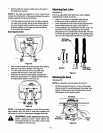
TypeB Battery
NOTE: The positive battery terminal is marked Pos. (+).
The negative battery terminal is marked Neg. (-).
• Place the battery on the battery plate with the
terminals toward the front of the tractor.
• Attach the positive cable (heavy red wire) to the
positive battery terminal (+) with hax bolt and hax
nut. See Figure 16. Slide the rubber boot over the
positive terminal.
• Remove hex bolt and nut from the negative cable.
Attach the negative cable (heavy black wire) to the
negative battery terminal (-) with the bolt and nut.
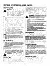
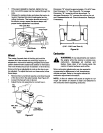
• Place the battery cover in position over the hold-
down rods. Secure with wing nuts, See Figure 17.
NOTE:/t may be necessary topull up on the hold-down
rods in order to start the wing nuts.
_.Hold-
Down
Battery Rod
Figure 17
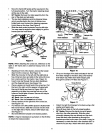
Route the battery drain tube (if equipped) over to
the left side of the tractor. Loosen the self-tapping
screw which secures the mounting clamp. See
Figure 18. Slip the end of the drain tube into the
mounting clamp. Tighten the self-tapping screw to
secure the clamp. Do not overtighten which could
collapse the drain tube.
NOTE: The vented battery allows any gases or liquid
from the battery to be drained onto the ground.
• Trim end of drain tube if more than 1 inch extends
below the frame.
O
Figure 18
FinalAssembly
• Make certain all nuts and bolts are tightened
securely.
13