


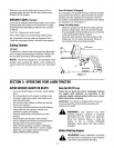
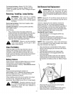
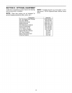


Remove the belt guards at each deck pulley by
removing the self-tapping screws. See Figure 23.
Self-Tapping Stabilizer Belt
Plate _uard
Belt Guard
Figure 23
Remove and replace the belt, reassemble following
the instructions in reverse order.
Deck Belts(46" Deck)
Place the liftlever in the engaged (all the way
forward) position.
Disconnect the spring which is attached to a
bracket on the transaxte, inside the right rear wheel.
Use a spring puller or other suitable tool.
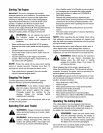
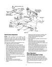
NOTE: When reassembling, make certain belt keeper
pins are assembled in the same locations from which
they were removed. See Figure 22.
Place the lift lever in the BLADES STOP position.
Remove the belt keeper pins from the lower frame.
See Figure 22.
Unhook the deck belt from the engine pulley.
Place the lift lever in the engaged (all the way
forward) position.
Disconnect the stabilizer plate from the stabilizer
shaft assembly by removing the hairpin clips and
flat washers and sliding out the rod. Refer to Figure
13.
Disconnect the six deck links by removing the
hairpin clips and flat washers.
Place the lift lever in the BLADES STOP position.
Slide the deck from beneath the lawn tractor.
Remove the top deck drive belt by lifting up on the
stabilizer plate, and slipping belt off the pulley.
Remove the belt cover at the two outside deck
pulleys, by removing the self-tapping screws.
Release the tension on the spring loaded idler by
pushing the idler toward the rear of the deck.
Remove the belt from around the idler pulleys, and
remove from the three deck pulleys.
Reassemble new belts, following instructions in
reverse order.
RearDrive Belt
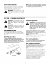
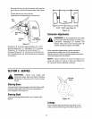
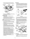
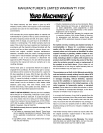
Place shift lever in neutral position. Unscrew the
shift knob and the speed control knob (if located on
the console). Remove the two truss head screws
which secure the transmission cover. See Figure
24.
Lift the transmission cover. Unplug the safety wire
from beneath the transmission cover. See Figure
24. Remove transmission cover.
Shift
Knob
Truss
Head Screws
Safety
Wire
Figure 24
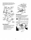
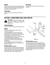
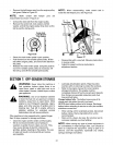
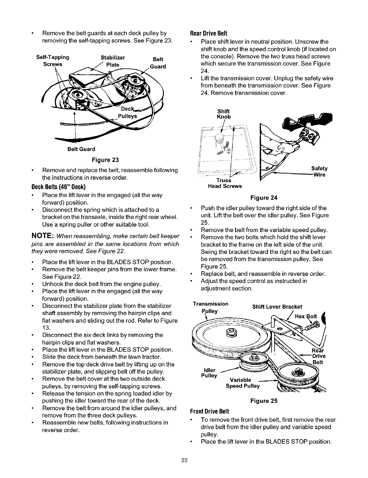
Push the idler pulley toward the right side of the
unit. Liftthe belt over the idler pulley. See Figure
25.
Remove the beltfrom the variable speed pulley.
Remove the two boltswhich hold the shift lever
bracket to the frame on the leftside of the unit.
Swing the bracket toward the right so the belt can
be removed from the transmission pulley. See
Figure 25.
Replace belt, and reassemble in reverse order.
Adjust the speed control as instructed in
adjustment section.
Transmission
dley
Shift Lever Bracket
Idler
Pulley
Variable
Speed Pulley
Belt
Figure 25
FrontDrive Belt
To remove the front drive belt, first remove the rear
drive belt from the idler pulley and variable speed
pulley.
Place the lift lever in the BLADES STOP position.
22