


GrassCollectorAvailable
Grass Collector Model OEM-190-063 is available as
optional equipment for lawn tractors with 38" and 42"
decks. Grass Collector Model OEM-190-103 is
available for lawn tractors with 46" decks.
WARNING: Do not operate the cutting
deck unless the discharge cover or entire
grass catcher are in the proper operating
position.
NOTE: Under normal usage bag material is subject to
wear, and should be checked periodically. Be sure to
use only factory authorized replacement bag.
SECTION4: MAKINGADJUSTMENTS
,_ WARNING: Never attempt to make any
adjustments while the engine is running,
except where specified in the operator's
manual.
WARNING: Disconnect the spark plug
wire(s) and ground against the engine before
performing any adjustments, repairs or
maintenance.
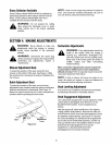
ManualAdjustmentSeat
To adjust the position of the seat, loosen the four
screws on the bottom of the seat. See Figure 2. Slide
the seat forward or backward as desired. Retighten the
four screws.
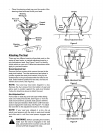
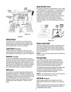
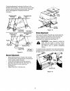
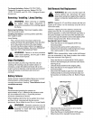
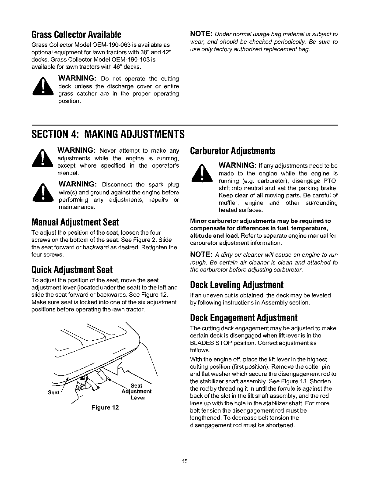
QuickAdjustmentSeat
To adjust the position of the seat, move the seat
adjustment lever (located under the seat) to the left and
slide the seat forward or backwards. See Figure 12.
Make sure seat is locked into one of the six adjustment
positions before operating the lawn tractor.
Seat
Adjustment
Lever
Figure 12
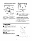
CarburetorAdjustments
WARNING: If any adjustments need to be
made to the engine while the engine is
running (e.g. carburetor), disengage PTO,
shift into neutral and set the parking brake.
Keep clear of all moving parts. Be careful of
muffler, engine and other surrounding
heated surfaces.
Minor carburetor adjustments may be required to
compensate for differences in fuel, temperature,
altitude and load. Refer to separate engine manual for
carburetor adjustment information.
NOTE: A dirty air cleaner will cause an engine to run
rough. Be certain air cleaner is clean and attached to
the carburetor before adjusting carburetor.
DeckLevelingAdjustment
If an uneven cut is obtained, the deck may be leveled
by following instructions in Assembly section.
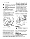
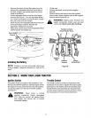
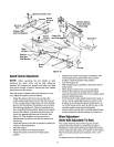
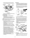
DeckEngagementAdjustment
The cutting deck engagement may be adjusted to make
certain deck is disengaged when lift lever is in the
BLADES STOP position. Correct adjustment as
follows.
With the engine off, place the lift lever in the highest
cutting position (first position). Remove the cotter pin
and flat washer which secure the disengagement rod to
the stabilizer shaft assembly. See Figure 13. Shorten
the rod by threading it in until the ferrule is against the
back of the slot in the lift shaft assembly, and the rod
lines up with the hole in the stabilizer shaft. For more
belt tension the disengagement rod must be
lengthened. To decrease belt tension the
disengagement rod must be shortened.
15