


To charge the battery: Battery P!N 725-1705D--
Charge at 2-3 amps for one hour. Battery P!N 725-
1707D, 725-0453G, and 725-1750--Charge at 6 amps
for one hour.
Removing/ Installing/ JumpStarting
_IL WARNING: When removing or installing
the battery, follow these instructions to
prevent the screwdriver from shorting against
the frame.
Removing the Battery: Disconnect negative cable
first, then positive cable.
Installing the Battery: Connect positive cable first,
then negative cable.
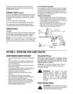
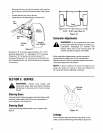
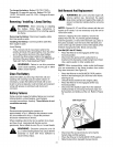
Jump Starting
First, connect end of one jumper cable to the
positive terminal of the good battery, then the other
end to the positive terminal of the dead battery.
Connect the other jumper cable to the negative
terminal of the good battery, then to the FRAME OF
THE UNIT WITH THE DEAD BATTERY.
WARNING: Failure to use this procedure
could cause sparking, and the gas in either
battery could explode.
CleanTheBattery
Clean the battery by removing it from the unit and
washing with a baking soda and water solution. If
necessary, scrape the battery terminals with a wire
brush to remove deposits. Coat terminals and exposed
wiring with grease or petroleum jelly to prevent
corrosion.
BatteryFailures
Some common causes for battery failure are: incorrect
initial activation, undercharging, overcharging,
corroded connections, freezing. These failures do not
constitute warranty.
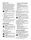
Tires
Recommended operating tire pressure is
approximately 10 p.s.i. Maximum tire pressure under
any circumstances is 30 p.s.L Equal tire pressure
should be maintained on all tires.
When installing a tire to the rim, be certain dm is clean
and free of rust. Lubricate both the tire and rim
generously. Never inflate to over 30 p.s.i, to seat beads.
WARNING: Excessive pressure (over 30
p.s.L) when seating beads may cause tire/rim
assembly to burst with force sufficient to
cause serious injury.
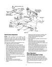
BeltRemovalAndReplacement
WARNING: Be sure to shut the engine off,
remove ignition key, disconnect the spark
plug wire(s) and ground against the engine to
prevent unintended starting before removing
belt(s)
NOTE: Figures 23, 27 and 28 are shown with the unit
tipped up for clarity. It is not necessary to tip the unit to
remove the belts.
However, if tipping the unit is desired, remove the
battery from the unit. To prevent gasoline leakage,
drain the gasoline, or remove the fuel tank cap, place a
thin piece of plastic over the neck of the fuel tank and
screw on the cap. Be certain to remove the plastic when
finished changing the belts. Block unit securely.
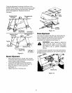
DeckBelt(38" And42" Decks)
Place the lift lever in the engaged (all the way
forward) position.
Disconnect the spdng which is attached to a
bracket on the transaxte, inside the dght rear wheel.
Use a spring puller or other suitable tool.
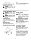
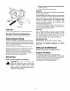
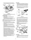
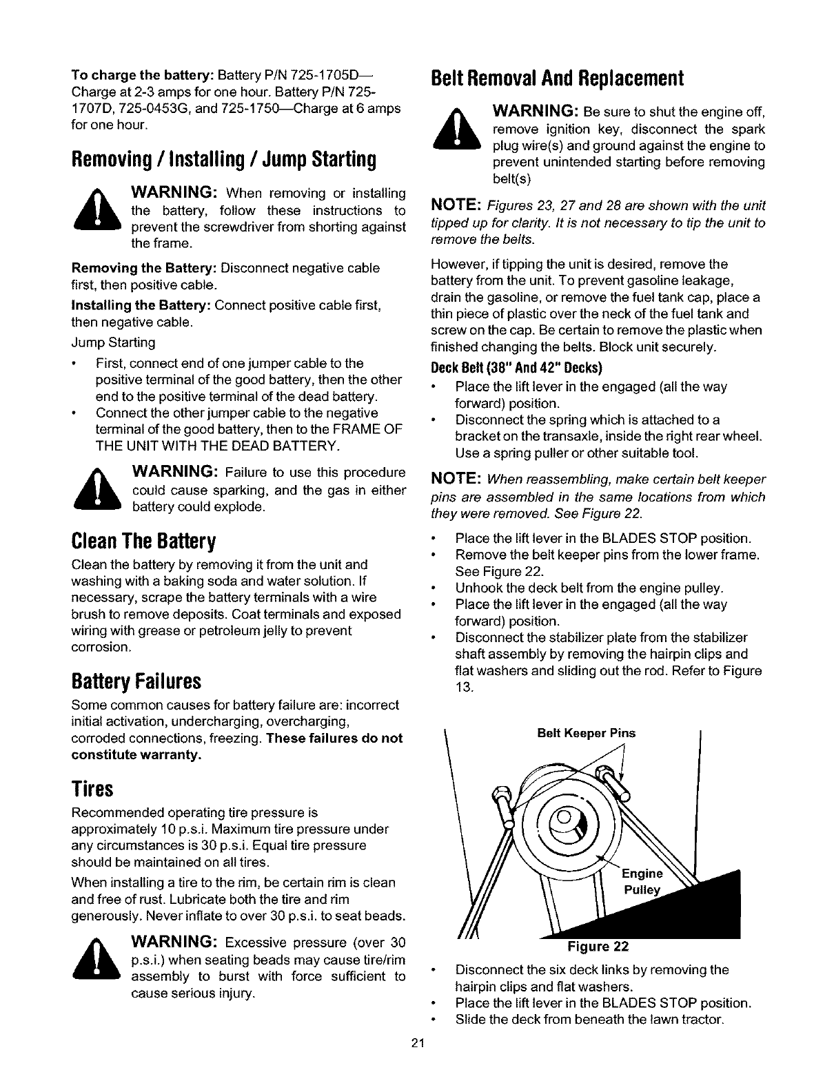
NOTE: When reassembling, make certain belt keeper
pins are assembled in the same locations from which
they were removed. See Figure 22.
Place the lift lever in the BLADES STOP position.
Remove the belt keeper pins from the lower frame.
See Figure 22.
Unhook the deck belt from the engine pulley.
Place the lift lever in the engaged (all the way
forward) position.
Disconnect the stabilizer plate from the stabilizer
shaft assembly by removing the hairpin clips and
flat washers and sliding out the rod. Refer to Figure
13.
Belt Keeper Pins
Figure 22
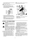
Disconnect the six deck links by removing the
hairpin clips and flat washers.
Place the lift lever in the BLADES STOP position.
Slide the deck from beneath the lawn tractor.
21